Transcription of EST3 Base Platform - Henry
1 Page 1 of 4 DATA SHEET 85010-0145 Not to be used for installation purposes. Issue 2 EST Catalog u EST3 Life safety Platform05-18-11 OverviewEST3 is a modular control Platform uniquely designed to meet the needs of applications ranging from standalone single panel fire alarm systems to multi-panel networks with unified fire alarm, security, access control and Mass Notification functions. Each function uses many of the same components, simplifying system all EST3 operating features are software-controlled. A powerful System Definition Utility program helps define system operations in a fraction of the time required by previous meth-ods. This gives EST3 great site flexibility and ensures operational changes and upgrades will be possible years after the initial instal-lation.
2 EST3 is uniquely designed to meet the life safety needs of any size facility. The function of each panel can be customized by using an extensive selection of plug and play local rail support for 64 nodes of up to 2,500 devices each, this network s multi-priority peer-to-peer token ring protocol delivers a fast alarm response time across any size network. Add to that the ability to network panels with fiber or copper connections with an overall length of 160000 ft - that s 30 miles - and you ve got virtu-ally unlimited networking Features Listed for Mass Notification/Emergency Communication, Fire, Security, Access Control, and Emergency Voice Alarm 168-character LCD Exceptional alarm response times Network supports copper, multi-mode fiber, single-mode fiber, or a combination of all three Total network wiring over 160,000 feet Eight channels of multiplexed digital audio on a single pair of wires or fiber filiment Zoned, distributed and banked audio amplifier options Local, Proprietary.
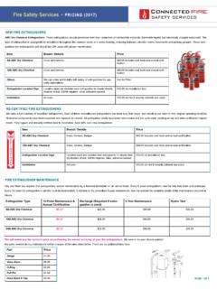
3 And Central Station system operations In retrofit applications, existing wiring may be used if code compliant Supports Edwards Signature Series detectors and modules Designed in accordance with ISO-9000 quality standards UL864 Ninth Edition Listed UL2572 Listed for Mass Notification Optional earthquake hardening: OSHPD seismic pre-approval for component Importance Factor Base PlatformWith Signature Series Fire AlarmThe EST3 is modularly listed under the following standards: UL 864 categories: UOJZ, UOXX, UUKL and SYZV, UL 294 category ALVY, UL 609 category AOTX, UL 636 category ANET, UL 1076 category APOU, UL 365 category APAW, UL 1610 category AMCX, UL 1635 category AMCX, UL2572 Mass listed to ULC-S527, ULC-S303, and 2 of 4 DATA SHEET 85010-0145 Not to be used for installation purposes.
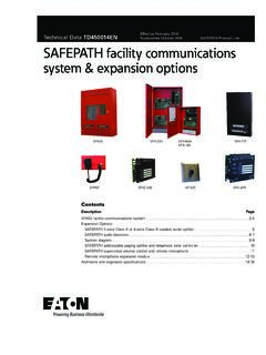
4 Issue 2 Outstanding FeaturesEST3 system components are arranged in layers, starting with the backbox and finishing with inner and outer doors. Cabinets are available with room for up to 20 modules and system batteries up to 65 AH. A single 24-volt battery can act as the secondary power supply for all four internal power supplies. Once the backbox is installed, up to four power supplies can be installed in the chassis assembly. The power supplies use a unique paralleling arrange-ment that ensures the optimum use of each supply. Each supply has the capacity to deliver up to 7 amps at 24 Vdc (28 amps total).The function of each life safety network panel is determined by the Local Rail Modules (LRMs) plugged into the panel s chassis.
5 An extensive variety of modules are avail-able, including central processing units, input/output circuit modules, communica-tion modules, secu-rity/access control modules, and audio amplifier modules. The top layer of the LRMs is referred to as the user interface layer. This layer is made up of the Main Display Interface module and a system of generic control/display modules. Any control/dis-play module can mount on any LRM. This maximizes flexibility of design for custom systems. The inner and outer doors finish and secure the single panel can support up to 2,500 addressable points, provide 28 amps @ 24 Vdc, provide access control for up to 124 doors, and still have room for future expansion. If a single panel is not large enough or you need to distribute functionality throughout the project, then you can network up to 64 panels together!
6 Networking/CommunicationsThe EST3 Life safety Network uses a multi-priority peer-to-peer token ring protocol. The protocol gives EST3 the exceptionally fast alarm response time of less than three seconds across the network, virtually independent of the total number of nodes. The EST3 token ring network configuration also affords long distances between panels. The distance between any three panels on #18 AWG ( mm ) is 5,000 ft (1,523m) for both network control and digital audio signals. Supporting a maximum of 64 panels on a network, the total network length can be in excess of 160000 ft (48768m). Network and audio communication are via RS-485 serial ports. Each two-wire circuit supports Class A (Style 7) or Class B (Style 4) wiring configurations.
7 Fiber optic media is also available. As an indication of the high level of system integration, off-premise communications is handled by the Modcom modem communica-tor module. This module provides the Digital Alarm Communicator Transmitter (DACT) function, sending system status signals for up to 255 accounts to up to 80 different central monitoring stations and/or commercial paging carriers. The Modcom also acts as a modem for uploading and downloading of system access control data remotely via the telephone AudioEST3 digitized audio can deliver up to eight audio messages simultaneously over a single pair of wires! This is plenty of capacity for both live and pre-recorded messages. EST3 easlly supports the needs of mass notification messaging, and fire alarm messag-ing by providing the ability to bring not only pre-recorded messag-es but also live voice messaging supporting not only evacuation announcments but the messaging needed to support the risks that may require shelter-in-place and relocation messaging.
8 All audio messages and live pages originate at the Audio Source Unit (ASU) that can store up to 100 minutes pre-recorded audio messages as .wav files. These mes-sages can be auto-matically directed to various areas in a fa-cility under program control. On the receiving end, zoned amplifiers installed in remote fire alarm cabinets receive and decode the dig-ital messages. The messages are then amplified and sent out to the speakers. The availability of eight different channels opens a number of new simultaneous notification possibilities:1) Live voice page for MNEC or fire-related instructions;2) Emergency floor evacuation/notification message;3) Alert message on floors above and below the emergency;4) Stairwell evacuation reinforcement message;5) Elevator cab information messages;6) Lobby message instructing occupants to exit the building;7) Concourse instructions to occupants not to enter the lobby;8) Other instructions to areas not directly affected by the combination of the eight audio channels can be automatically directed to any or all areas of the building, with total manual over-ride as required.
9 Eight channel capability assures that one mes-sage is never interrupted in order to process another, a common fault with two-channel systems. This eliminates any chance of confusing the occupants with conflicting is also an integral part of EST3 s digitized audio system. Default audio messages are continuously transmitted to all network amplifiers by the ASU. These messages provide audio supervision for the digital audio chain, and act as a default signal if the network data circuit fails or should message control infor-mation fail to reach the ASU. If the audio data circuit fails, each amplifier generates a 1 KHz temporal (3-3-3) tone that is transmit-ted during an alarm. In the event of an amplifier failure, a backup audio amplifier is automatically substituted for the failed amplifier in the cabinet, restoring audio capability.
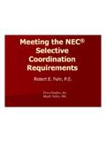
10 In the unlikely event of multiple amplifier failures, the backup amp replaces the amplifier actively processing the highest priority message in the cabinet. When messages are no longer directed to a failed amplifier such as when a high priority page message ends, the backup amp is dynamically reassigned to the next highest priority failed amplifier actively processing messagesBOXLOCALRAILMODULESCHASSISCONTRO LDISPLAYMODULESINNERDOORCOVEROUTERDOORPa ge 3 of 4 DATA SHEET 85010-0145 Not to be used for installation purposes. Issue 2 Typical WiringFFMMCCCCCCMMMMJJSJJJCRCRCRFJFFF2 Tw. Tw/Sh Tw. Tw/Sh Tw/Sh Pr & 2 Tw/Sh Pr &2 Tw/Sh Tw/Sh Tw/Sh Pr &2 Tw/Sh Pr3 next remotefloor panel3 FLOOR2nd FLOORP rimaryPowerSource4th FLOORN etwork control,audio, & telephoneWATERFLOW SWITCHELEVATOR CAPTURE HVAC CONTROLHVACCONTROLHVAC MONITORHVACMONITORFIREDAMPERWATER LEVELMONITORCRITICAL PROCESSMONITORSPRINKLER SUPERVISORY SWITCHR emoteFloor Panel(Node)