Transcription of Establishment of a Lead-Free Reflow Soldering Technology ...
1 32 Oki Technical ReviewJuly 2004/Issue 199 of a Lead-Free Reflow Soldering Technology That Supports Components with Low Heat ResistanceMasahito NozueTakashi ObinataLead- free solders made of tin, silver and copper thathave become the mainstream solders, have meltingtemperatures between 217 and 220 C, which is 30 C ormore higher than conventional solders containing ovens that support Lead-Free Soldering commonlyused in automated Soldering processes adopt theconvection fan method as the means for heating tomaintain an evenly high internal temperature. For thisreason components were exposed to high temperatures,which meant that components with a lower thermalresistance could not be used. Further, uniform heattransfer was difficult with multilayer and large scale, highdensity, package mounted substrates and ball grid array(BGA) terminal components that were used insophisticated communications equipment and copyingmachines.
2 Therefore, connection failure often occurredand common Lead-Free compatible Reflow ovens could notbe used. These components needed to be replaced withalternative components with a high thermal resistance ormounted individually afterwards manually or by usingspecial equipment. At Oki Electric, we have been able to establish afabrication method that resolves such problems related tolead- free Soldering , by jointly developing a componenttemperature rise controlled Reflow Technology with theFurukawa Electric Co., Ltd. This Technology adopts a newheating method, which realizes the automatic Soldering ofelectronic components that have a low thermal resistanceby inhibiting the temperature rise of of Lead-Free conversion activitiesThere is a worldwide movement to regulate the use oflead, due to its harmful effects on the human body.
3 Particularly in Europe, with the restricted use ofcertain hazardous substances (RoHS), a regulation tostop the use of harmful chemical substances will beginfrom July 2006. The means to respond to the regulationrestricting the use of solder containing lead is a majorconcern for corporate organizations dealing withelectrical equipment and electronic Oki Electric an environmental conservation activityprogram known as OKI Eco Plan 21 was established,with a target to totally abolish solder containing leadfrom major products by the end of fiscal 2003 . Theestablishment of technologies to attain this target hasbeen promoted from the early stages. The component temperature rise controlled reflowsoldering Technology , reported in this paper, is one resultof such for selecting Sn-Ag-Cu-type Lead-Free solderHigh reliability is demanded of Soldering materialsthat are used in communications equipment requiring along product life.
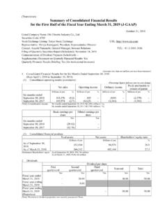
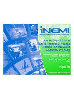
4 For this reason, comparison studieswere made on items, such as those described in Table 1,keeping in mind that these materials need to have thefollowing characteristics: (1) Highly reliable materials(2) Same material usable in all processes(3) Industry standard materials(4) Avoid factors that contribute to an increase in costs,such as patents As a result, the Soldering material withits high connection reliability was 1 Lead-Free solder selection resultSince an aspect of the Soldering material is its highmelting temperature, Soldering equipment that can heatuniformly at a high temperature will be to support low thermal resistance components(1) Aspects of Reflow solderingThe common method for Soldering components ontoa substrate is by mounting components on a preprintedsubstrate and the heating the entire substrate to remeltthe solder .
5 This type of Soldering method is called reflowsoldering (Fig. 1).If the melting temperature rises, such as with Lead-Free solders, then correspondingly, the temperature of theentire substrate also needs to be raised, making thecomponent temperatures high at the same time. A reflowoven of about eight meters in overall length is used forheating with heaters above and below a conveyer thatcarries the in all processesFlow/ Reflow /manual solderingWorkabilityConnection reliabilityEffects of lead containing componentsSolder wetting characteristicsSolder melting temperatureItem Lead-Free conversion issuesRise of melting temperature due to change of compositionDeteriorated solder wetting characteristics due to reduced fluidity and increased surface tensionAlloy layer changes due to change in composition metalsLiftoff arising from the difference in the melting points of composition metalsOxidation progression of composition metalsConnectivity when combined with existing componentsOxidation progression of composition metalsEutectic solder183 CPossible-Good-High
6 GoodLead- free solder217 ~ 220 CInferiorPossibleGoodRareHigh SmallSn-Ag-Cu-xx-type210 ~ 217 CGoodPossibleGoodOftenLowMediumSn-Zn(-xx )-type189 ~ 198 C-LowBadBad (rapid oxidation)LargeReflow not possibleSn-Ag-Cu-type (JEITA) recommended compositionMelting temperature is highSpecial Issue on Human Friendly TechnologiesOki Technical Review33 July 2004/Issue 199 1 Summary of Reflow solderingHeating methods vary among manufacturers in termsof types and the number of heaters used, the heatingatmosphere, etc., however, the convection fan method isthe common type used for Lead-Free Soldering .(2) Thermal resistance of components and 230 ClimitationSubstrates for communication equipment producedby Oki Electric have the following features:1) Substrates have a long product life ) Wide range of substrates produced in a small ) Many components have a thermal resistance of230 C or ) Large sizes, multiple layers and high densities (withmany mounted BGAs).
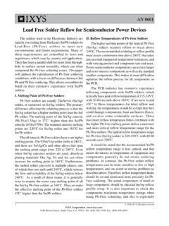
7 For these reasons, it is extremely difficult to takesteps, such as changing components or substratedesign, when conducting high temperature Reflow forlead- free Soldering . Fig. 2 Reflow thermal resistance temperature and number of component typesA survey of the thermal resistance temperature ofcomponents used, resulted in a finding that about 45% ofall component types had a thermal resistancetemperature of 230 C or less, as indicated in Fig. most of these components are ICs, which aredifficult to switch to alternative components, thecomponent temperatures must be kept at or below 230 Cto conduct Reflow manual Soldering is one of the fabricationmethods that can be used instead of Reflow Soldering forcomponents with a low thermal resistance, it would leadto a deterioration in quality due to variations arising fromthe work and, since also may be a contributing factor to arise in costs, it would not be a realistic heating process marginWhile conventional eutectic solder Reflow a varianceof up to 47 C can be tolerated in the substrate heatingtemperature, between the thermal resistance ofcomponents to 230 C and the solder melting point of183 C.
8 On the other hand, with Lead-Free Soldering only10 C can be tolerated between the thermal resistance ofcomponents to 230 C and a solder melting temperatureof between 220 and 217 C (Photo 1 and Fig. 3).Phot. 1 Reflow temperatures and conditions of solderingFig. 3 Comparison of temperature margins of Lead-Free solder and eutectic solderCurrent levels and target settingAs part of a study into the process for lead-freesoldering, the performance of Reflow ovens, manufacturedby various companies, was investigated using substratesfor communication equipment. As a result it was foundthat although the variance of the substrate's internaltemperature for conventional Reflow ovens supportingeutectic solders (high temperature portions: Componentbodies; low temperature portions: Temperature differenceat soldered sections) was 18 C, commonly availablereflow ovens for Lead-Free solders had a substrate internaltemperature variance of 12 C (Fig.)
9 4).Fig. 4 Comparison of the temperature variance between substratesSolderPrintingHeatMounting componentFinishDistribution of the thermal resistance temperature for Reflow components200 220 225 230 235 240 245 250 255 260 265 270 Thermal resistance temperature ( C)Number of component typesBonding temperature: 220 CNon-melting of solder occursBonding temperature: 225 C and higherFavorable solderingBonding temperature: 220 CNon-melting of solder occursBonding temperature: 225 C and higherFavorable solderingApprox. 10 CTemp230 C200 CLead- free solderSn - - 50 CFuture trendThermal resistance increasing direction of the trends of components manufacturers: 250 CCurrent component thermal resistance: 230 CMelting temperature: 217 C to 220 CMelting temperature: 183 CEutectic solder63Sn - 37 PbExample of eutectic solder Reflow profile Example of Lead-Free solder Reflow profileControl of the heating process is extremely difficult T (variance of the substrate's internal temperature) 0220230240250( C)212 CConventional eutectic Soldering Reflow oven(far infrared radiation combined method)230 CCommon Lead-Free Soldering Reflow oven(convection fan method)242 C230 C: Component body.
10 Soldering section220 C and above Joint section temperatureComponent thermal resistance230 C and belowIt is difficult to control the temperature to within a range of T < 10 C in a uniform heating Technical ReviewJuly 2004/Issue 199 in mind that the temperature margin of Lead-Free Soldering must be 10 C or less, the actualdevelopment target was set with a substrate internaltemperature variance of 10 C or less. For this reason, inorder to inhibit the rising temperature of components andby taking an inverse action, the temperature variancewas intentionally created on the top and bottom surfacesof the substrates, resulting in a heating method thatmakes it possible to bring about: Component temperature < Soldering a basic structure for a component temperature rise controlled Reflow ovenFig.