Transcription of etherchannel - Router Alley
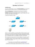
1 etherchannel Aaron Balchunas 1. - etherchannel - Port Aggregation A network will often span across multiple switches. Trunk ports are usually used to connect switches together. There are two issues with using only a single physical port for the trunk connection: The port represents a single point of failure. If the port goes down, the trunk connection is lost. The port represents a traffic bottleneck. All other ports on the switch will use that one port to communicate across the trunk connection. Thus, the obvious benefits of adding redundancy to the trunk connection are fault tolerance and increased bandwidth, via load balancing.
2 However, simply trunking two or more ports between the switches will not work, as this creates a switching loop. One of two things will occur: Spanning Tree Protocol (STP) will disable one or more ports to eliminate the loop. If STP is disabled, the switching loop will result in an almost instantaneous broadcast storm, crippling the network. Port aggregation allows multiple physical ports to be bundled together to form a single logical port. The switch and STP will treat the bundled ports as a single interface, eliminating the possibility of a switching loop.
3 Cisco's implementation of port aggregation is called etherchannel . etherchannel supports Fast, Gigabit, and 10 Gigabit Ethernet ports. A maximum of 8 active ports are supported in a single etherchannel . If the ports are operating in full duplex, the maximum theoretical bandwidth supported is as follows: Fast Ethernet 1600 Mbps Gigabit Ethernet 16 Gbps 10 Gigabit Ethernet 160 Gbps The maximum number of supported EtherChannels on a single switch is platform-dependent, though most support up to 64 or 128 EtherChannels. **. All original material copyright 2014 by Aaron Balchunas unless otherwise noted.
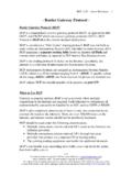
4 All other material copyright of their respective owners. This material may be copied and used freely, but may not be altered or sold without the expressed written consent of the owner of the above copyright. Updated material may be found at etherchannel Aaron Balchunas 2. etherchannel Requirements The previous section described the benefits of port aggregation for a trunk connection. However, EtherChannels can be formed with either access or trunk ports. EtherChannels are also supported on Layer-3 interfaces. Implementing an etherchannel for access ports provides increased bandwidth and redundancy to a host device, such as a server.
5 However, the host device must support a port aggregation protocol, such as LACP. Port aggregation protocols are covered in great detail later in this guide. Similarly, implementing etherchannel for trunk connections provides increased bandwidth and redundancy to other switches. If a port in an etherchannel bundle fails, traffic will be redistributed across the remaining ports in the bundle. This happens nearly instantaneously. For an etherchannel to become active, all ports in the bundle must be configured identically, regardless if the etherchannel is being used with access or trunk ports.
6 Port settings that must be identical include the following: Speed settings Duplex settings STP settings VLAN membership (for access ports). Native VLAN (for trunk ports). Allowed VLANs (for trunk ports). Trunking encapsulation protocol (for trunk ports). On trunk connections, the above settings must be configured identically across all participating ports on both switches. Historically, port-security has not been supported on an etherchannel . Newer platforms may provide support as long as port-security is enabled on both the physical interfaces and the etherchannel itself.
7 **. All original material copyright 2014 by Aaron Balchunas unless otherwise noted. All other material copyright of their respective owners. This material may be copied and used freely, but may not be altered or sold without the expressed written consent of the owner of the above copyright. Updated material may be found at etherchannel Aaron Balchunas 3. etherchannel Load-Balancing Traffic sent across an etherchannel is not evenly distributed across all ports in the bundle. Instead, etherchannel utilizes a load-balancing algorithm to determine the port to send the traffic out, based on one of several criteria: Source IP address - src-ip Destination IP address - dst-ip Source and destination IP address - src-dst-ip Source MAC address - src-mac Destination MAC address - dst-mac Source and Destination MAC address - src-dst-mac Source TCP/UDP port number - src-port Destination TCP/UDP port number - dst-port Source and destination port number - src-dst-port Using a deterministic algorithm prevents perfect load-balancing.
8 However, a particular traffic flow is forced to always use the same port in the bundle, preventing out-of-order delivery. The default load-balancing method for a Layer-2 etherchannel is either src- mac or src-dst-mac, depending on the platform. The default method for a Layer-3 etherchannel is src-dst-ip. The load-balancing method must be configured globally on the switch: Switch(config)# port-channel load-balance src-dst-mac To display the currently configured load-balancing method: Switch# show etherchannel load-balance etherchannel Load-balancing Configuration: src-dst-mac To view the load on each port in an etherchannel (output abbreviated): Switch# show etherchannel 1 port-channel Index Load Port EC state ------+------+--------+------------ 0 55 Gi2/23 active 1 3A Gi2/24 active The load is rather cryptically represented in a hexadecimal value.
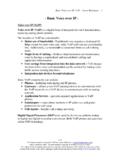
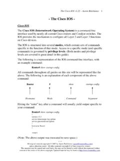
9 (Reference: ). **. All original material copyright 2014 by Aaron Balchunas unless otherwise noted. All other material copyright of their respective owners. This material may be copied and used freely, but may not be altered or sold without the expressed written consent of the owner of the above copyright. Updated material may be found at etherchannel Aaron Balchunas 4. etherchannel Load-Balancing Example Consider the following example, where ports gi2/23 and gi2/24 on both switches are members of an etherchannel : Assume that the load-balancing method is src-ip.
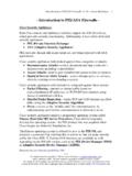
10 The first port in the etherchannel will become Link0; the second will become Link1. The two links in the etherchannel can be represented in one binary bit. The load-balancing algorithm will create an index that associates Link0 with a binary bit of 0, and Link1 with a bit of 1. As traffic passes through the etherchannel , the algorithm will convert the source IP addresses into a binary hash, to compare against the index. For example, consider the following IP addresses and their binary equivalents: Because there are only two ports in the etherchannel , only one bit needs to be considered in the IP address the last bit.