Transcription of EV Series - Aqua T
1 DisinfectionINSTALLATION & OPERATION MANUALThis manual covers installation, operation and maintenancerequirements for ATS Disinfection Systems. Model EV-8E, 12E, 20E(During normal operation, the Green LED will flash every 5 - 10 seconds.)It is important that those responsible for the installation of thisequipment, as well as the owner / operator, read this manualand carefully follow the instructions and : 5/11EV Series AQUA TREATMENT SERVICE, HEMPT ROADMECHANICSBURG, PA 17050ph: (717) 697 - 4998fax: (717) 697 - 5035 EPA PRODUCT REGISTRATION #062333-PA-001 2 SAFETY INSTRUCTIONSWARNING - to guard against injury, basic safety precautions should be observed, including the following:1. READ AND FOLLOW ALL SAFETY DANGER - To avoid possible electric shock, special care should be taken since water is present near electrical equipment.
2 Unless a situation is encountered that is explicitly addressed by the provided maintenance and troubleshooting sections, do not attempt repairs yourself, refer to an authorized service Carefully examine the disinfection system after installation. It should not be plugged in if there is water on parts not intended to be Do not operate the disinfection system if it has a damaged power cord or plug, if it is malfunc-tioning or if it is dropped or damaged in any Always disconnect water flow and unplug the disinfection system before performing cleaning or maintenance activities. Never yank the power cord to remove it from an outlet. Grasp the plug and pull to Do not use this disinfection system for other than the intended use (potable water applications.)
3 The use of attachments not approved, recommended or sold by the manufacturer / distributor may cause an unsafe Intended for indoor use. Do not install this disinfection system where it will be exposed to the weather. Do not store this disinfection system where it will be exposed to temperatures below freezing unless all the water has been drained from it and the water supply has been Read and observe all the important notices and warnings on the water disinfection If an extension cord is necessary, a cord with a proper rating should be used. A cord rated for less Amperes or Watts than the disinfection system rating may over heat. Care should be taken to arrange the cord so that it will not be tripped over or accidentally pulled from the SAVE THESE : The light given off by this unit can cause serious burns to unprotected eyes and skin.
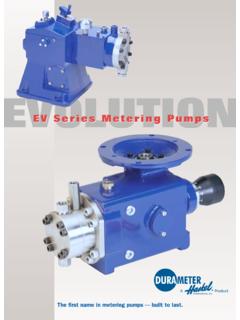
4 Never look directly at a lit UV lamp. When performing any work on the UV Disinfection System, always unplug the unit first. Never operate the UV system while the lamp is outside of the UV : The UV lamp inside of the disinfection system is rated at an effective life of approx-imately 9,000 hours. To ensure continuous water treatment, replace the UV lamp annually with the appropriate Aqua Treatment Services UV lamp. Failure to comply may present a fire hazard. 3 FUNCTION:The function of this ultraviolet disinfection unit is to provide in excess of 99% reduction of all water borne pathogenic (disease causing) EV Series have a number code designation correspondent to the maximum gpm (gallons per minute) flow rate of the unit.
5 EV-8E has a maximum flow capacity of 8 :Ultraviolet Germicidal Ultraviolet Disinfection Units are designed to destroy micro-organisms in water supplies. The Ultraviolet lamp peak radiation of 254 nanometer wavelength (nm) destroys or inactivates the (deoxyribonucleic acid) which absorbs the Ultraviolet radiation. Germicidal Disinfection units meet minimum dosages of 30,000 microwatt second per square CONCENTRATION LEVELS BEFORE NTU gpg ppm - Note - Pre-filtration equipment may be required if these parameters cannot be maintained. Flow rate must not exceed rated capacity of the OF EQUIPMENT:The EV Series has an unique design with an ultraviolet germicidal lamp housed within a single quartz sleeve surrounded by a stainless steel pressure chamber.
6 The chamber is fabricated out of 304 Stainless Steel. These units come with an ultraviolet lamp designed with four pins at one quartz sleeve is intended to be placed through the disinfection chamber and will slightly protrude through the threaded nipple. The ultraviolet lamp is placed within this quartz sleeve. The light shines through this specially designed hard quartz sleeve for maximum disinfection efficiency to meet the requirements for bacteria reduction in potable inlet/outlet are located on one side of the chamber and may be interchanged as to designation dependent upon installation. A Site Port is provided for safe and easy view of operation. A box is secured to the wall and the chamber is held in place by tightening the lock nut to both mounting box and chamber.
7 4 GENERAL CONSIDERATIONS FOR ALL DISINFECTION UNITS:1. When installing the equipment, it is necessary that the unit be isolated from vibration, heavy equipment, and poorly connected Incoming water temperature to the unit should not exceed 35 minimum to110 maximum degrees The operating pressure should not exceed 100 Before putting the unit into final operation follow sanitation procedures as outlined in this manual for proper disinfection. Sanitizing all discharge piping and fittings with household bleach from disinfection unit to point of use removes existing contaminants and gives the unit a clean start. Be sure to rinse with treated A proper flow control must be used to insure only the designated flow through the unit.
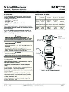
8 GENERAL PRECAUTIONS TO BE FOLLOWED AT ALL TIMES: 1. Always disconnect electrical power to any unit before servicing. 2. Under no circumstances should personnel look at a lamp in operation. (EXCEPT through an external Site Port lens located on the outside of the unit). 3. disinfection units must always be properly :The EV Series are always placed after the pressure tank and any other type of treatment devices ( softeners, filters).These units are normally installed in a vertical position in an enclosed area with good ventilation. Allow clearance of at least the unit s length at one end for quartz sleeve and bulb replacement. Two (2) anchor bolt holes are provided for proper wall support.
9 Use wall plugs with screws for sufficient support (not included). A lock nut secures the mounting box to the your piping system is subject to impulse pressure resulting in a water hammer condition, a surge tank or other means must be provided to remove this condition; otherwise, this extreme shock pressure condition may rupture or fracture the quartz all plumbing connections to allow for ease of service. Be sure to follow all local plumbing codes and restriction requirements where specified by local electrical control box is vented to allow proper air ventilation to components. For outdoor applica-tions install a protective rain guard shield (contact your UV supplier for part number) to prevent water from direct contact with the control box.
10 The rain guard is not necessary for indoor applications. 5 STEP BY STEP INSTALLATION: 1. Turn off the water before cutting into the water line. 2. Assess the installation ( type of pipe, size of lines, etc.) and obtain necessary plumbing fittings for installation. Inlets and outlets on 8 gpm units are 3/4" MNPT. Use Teflon tape on all threaded connections and avoid over tightening. Note: The flow control is a press in type. Each unit has a 3/4" MNPT inlet/outlet machined so the press in flow control can be easily inserted into whichever port you select for the inlet. Make sure the rubber part of the flow control is facing outward from the port selected. Simply hand press or slightly tap in the flow control until it sits on the inside ledge of the machined port.