Transcription of Everything You Always Wanted to Know About the …
1 1 SemiconductorCopyright Harris Corporation 1998 Everything You Always Wanted to KnowAbout the ICL8038 IntroductionThe 8038 is a function generator capable of producing sine,square, triangular, sawtooth and pulse waveforms (some atthe same time). Since its introduction, marketing and appli-cation engineers have been manning the phones explainingthe care and feeding of the 8038 to customers experience has enabled us to form articulate responsesto the most frequently asked questions. So, with data sheetand breadboard in hand, read on and be 1I want to sweep the frequency externally but can only get arange of 100:1 (or 50:1, or 10:1). Your data sheet says1000:1. How much sweep range can I expect?AnswerLet s look at what determines the output frequency. Start byexamining the circuit schematic at pin 8 in the upper left handcorner.
2 From pin 8 to pin 5 we have the emitter-base of NPNQ1and the emitter-base of PNP Q2. Since these two diodedrops cancel each other (approximately), the potential at pins8, 5, and 4 are the same. This means that the voltage from V+to pin 8 is the same as the voltage across external resistorsRAand RB. This is a textbook example of a voltage acrosstwo resistors which produce two currents to charge and dis-charge a capacitor between two fixed voltages. This is also alinear system. If the voltage across the resistors is droppedfrom 10V to 1V, the frequency will drop by 10:1. Changingfrom 1V to will also change the frequency by 10 , by causing the voltage across the external resis-tors to change from say 10V to 10mV, the frequency can bemade to vary at least 1000:1. There are, however, several fac-tors which make this large sweep range less than 2 You say I can vary the voltage on pin 8 (FM sweep input) toget this large range, yet when I short pin 8 to V+ (pin 6), theratio is only around 100 is often true.
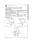
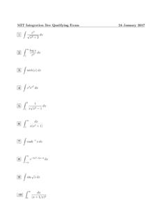
3 With pin 8 shorted to V+, a check on thepotentials across the external RAand RBwill show 100mVor more. This is due to the VBEmismatch between Q1andQ2(also Q1and Q3) because of the geometries and currentlevels involved. Therefore, to get smaller voltages acrossthese resistors, pin 8 must be raised above V+.Question 3 How can I raise pin 8 above V+ without a separate powersupply?AnswerFirst of all, the voltage difference need only be a few hundredmillivolts so there is no danger of damaging the 8038. Oneway to get this higher potential is to lower the supply voltageon the 8038 and external resistors. The simplest way to dothis is to include a diode in series with pin 6 and resistors RAand RB. See Figure 1. This technique should increase thesweep range to 1000 , now I can get a large frequency range, but I notice thatthe duty cycle and hence my distortion changes at the low-est is caused partly by a slight difference in the VBEsofQ2and Q3.
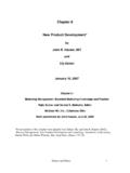
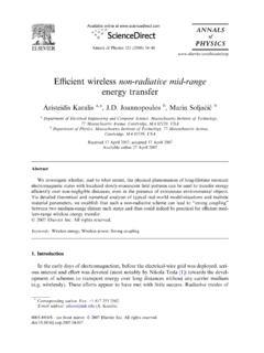
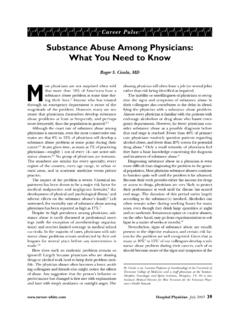
4 In trying to manufacture two identical transistors, it isnot uncommon to get VBEdifferences of several millivolts ormore. In the standard 8038 connection with pins 7 and 8 con-nected together, there are several volts across RAand RBandthis small mismatch is negligible. However, in a swept modewith the voltage at pin 8 near V+ and only tens of millivoltsacross RAand RB, the VBEmismatch causes a larger mis-match in charging currents, hence the duty cycle changes. Forlowest distortion then, it is advisable to keep the minimumvoltage across RAand RBaround 100mV. This would ofcourse, limit the frequency sweep range to around 100 1. VARIABLE AUDIO OSCILLATOR, 20Hz TO F+ F100K10M100 KFREQUENCYLOG POT234567891011 12 Application NoteNovember : Bill O Neil2 Question 5I have a similar duty cycle problem when I use high values ofRA and RB.
5 What causes this?AnswerThere is another error term which becomes important at verylow charge and discharge currents. This error current is theemitter current of Q7. The application note on the 8038 givesa complete circuit description, but it is sufficient to know thatthe current charging the capacitor is the current in RAwhichflows down through diode Q9and into the external C. Thedischarge current is the current in RBwhich flows downthrough diode Q8. Adding to the Q8current is the current ofQ7which is only a few microamperes. Normally, this Q7cur-rent is negligible, but with a small current in RB, this currentwill cause a faster discharge than would be expected. Thisproblem will also appear in sweep circuits when the voltageacross the external resistors is 6 How can I get the lowest distortion over the largestfrequency sweep of all, use the largest supply voltage available ( 15V or+30V is convenient).
6 This will minimize VBEmismatch prob-lems and allow a wide variation of voltage on pin 8. Thepotential on pin 8 may be swept from VCC(and slightlyhigher) to 2/3 VCC+2V) where VCCis the total voltageacross the 8038. Specifically for 15V supplies (+30V), thevoltage across the external resistors can be varied from 0 Vto nearly 8V before clipping of the triangle waveform , keep the maximum currents relatively large (1mA or2mA) to minimize the error due to Q7. Higher currents couldbe used, but the small geometry transistors used in the 8038could give problems due to VCE(SAT)and bulk resistance, , and this is important, use two separate resistors for RAand RBrather than one resistor with pins 4 and 5 connectedtogether. This is because transistors Q2and Q3form a differ-ential amplifier whose gain is determined by the impedancebetween pins 4 and 5 as well as the quiescent current.
7 Thereare a number of implications in the differential amplifier con-nection (pins 4 and 5 shorted). The most obvious is that thegain determines the way the currents split between Q2andQ3. Therefore, any small offset or differential voltage willcause a marked imbalance in the charge and discharge cur-rents and hence the duty cycle. A more subtle result of thisconnection is the effective capacitance at pin 10. With pins 4and 5 connected together, the Miller Effect as well as thecompound transistor connection of Q3and Q5can produceseveral hundred picofarads at pin 10, seriously limiting thehighest frequency of oscillation. The effective capacitancewould have to be considered important in determining whatvalue of external C would result in a particular frequency ofoscillation.
8 The single resistor connection is fine for very sim-ple circuits, but where performance is critical, the two sepa-rate resistors for RA and RB are , trimming the various pins for lowest distortiondeserves some attention. With pins 7 and 8 connectedtogether and the pot at pin 7 and 8 externally set at its maxi-mum, adjust the ratio of RAand RBfor 50% duty cycle. Thenadjust a pot on pin 12 or both pins 1 and 12 depending onminimum distortion desired. After these trims have beenmade, set the voltage on pin 8 for the lowest frequency ofinterest. The principle error here is due to the excess currentof Q7causing a shift in the duty cycle. This can be partiallycompensated for by bleeding a small current away from pin5. The simplest way to do this is to connect a high value ofresistance (10M to 20M ) from pin 5 to V- to bring the dutycycle back to 50%.
9 This should result in a reasonable com-promise between low distortion and large sweep 7 This waveform generator is a piece of junk. The triangle waveis non-linear and has large glitches when it changes re probably having trouble keeping the constant voltageacross RAand RBreally constant. The pulse output on pin 9puts a moderate load on both supplies as it switches current onand off. Changes in the supply reflect as variations in chargingcurrent, hence non-linearity. Decoupling both power supply pinsto ground right at the device pins is a good idea. Also, pins 7and 8 are susceptible to picking up switching transients (this isespecially true on printed circuit boards where pins 8 and 9 runside by side). Therefore, a capacitor ( F or more) from V+ topin 8 is often advisable. In the case when the pulse output is notrequired, leave pin 9 open to be sure of minimizing 8 What is the best supply voltage to use for lowest frequencydrift with temperature?
10 AnswerThe 8038AM, 8038AC, 8038BM and 8038BC are all temper-ature drift tested at VCC= +20V (or 10V). A curve in thelower right hand corner of Page 4 of the data sheet indicatesfrequency versus temperature at other supply voltages. It isimportant to connect pins 7 and 8 9 Why does connecting pin 7 to pin 8 give the best temperatureperformance?AnswerThere is a small temperature drift of the comparator thresh-olds in the 8038. To compensate for this, the voltage dividerat pin 7 uses thin film resistors plus diffused resistors. Thedifferent temperature coefficients of these resistors causesthe voltage at pins 7 and 8 to vary to maintainoverall low frequency drift at VCC= 20V. At higher supplyvoltages, , 15V (+30V), the threshold drifts are smallercompared with the total supply voltage.