Transcription of EVINRUDE AND JOHNSON 5 AND 6 HP (1965-1968)
1 SERVICE MANUALE vinrude & JOHNSON 5 & 6 HPEVINRUDE AND JOHNSON 5 AND 6 HP (1965-1968) EVINRUDEYear Produced 5 hp 6 hp1965 5502,5503 6502,65031966 5602,5603 6602,66031967 5702, 5703 6702, 67031968 5802, 5803 6802.
2 6803 CONDENSED SERVICE DATATUNE-UPHp @ rpm. @ 4000 @4500 Bore Inches lfj IffStroke Inches V/i 1V&Number of Cylinders 2 2 Displacement Cu. In PlugChampion J4J J4 JAC M42K M42 KAutolite A21X A21 XElectrode Gap Gap Own OwnFuel OU Ratio
3 50:1 50:1 SEES CLEARANCESP iston RingsEnd Gap Clearance Skirt Clearance Bearings DiameterTop Main Bearing Main Beariag Main Bearing ^6690 Crankshaft Bearings Diametral ClearanceTop Main Bearing Main Bearing
4 Main Bearing Roller BearingCrankshaft End Play Max. Pin DiametralClearance In Rod TORQUES(AU Values in Inch Pounds)Connecting Rod 60-66 60-66 Crankixtse Halves 60^80 60-80 Cylinder Head 60-80 60-80 Exhaujst Cover 24-36 24-36 Hywheel Nut 480-540 480-540 Intake Manifold 24-36 24-36 Spark Plug
5 240-246 240-246 JOHNSON5hpLD-10, LDL-10LD-11,LDL-11LD-12, LDL-12LD-13, LDL-136hpCD 22, CDL-22CD 23, C0L-23(JD-24, CDL-24(:D-25, CDL-25 LUBRICATIONThe power head is lubricated by oil mixedwith the fuel Use Vs pint of oil with eachgallon of regular automotive or white marinegasoline. A good quality Outboard MotorOil is recommended; if outboard oil is notavailable, use Type l^M, SAE 30 AutomotiveMotor Oil. Use double the recommendedamount of oil in 1hi^ mixture with a newmotor or after overhaul. Mix oil and gaso-line thoroughly, using a separate container,before pouring mixture into fuel lower unit gears and bearings arelubricated by oil contained in the gear "Outtoard Marine Corporation, TypeC Lubricant" should be used.))
6 This lubricantis supplied in a tube? and filling proceduresare as follows: Remove lower plug fromgear case and attach tube. Remove upper(vent) plug from case and, with motor in anupright position, fill gear case until lubri-cant reaches level of upper (vent) plug vent plug; then remove lubricanttube and reinstall lower plug. Tighten bothplugs securely, using new gaskets if neces-sary, to assure a water-tight seal. If OMCType C Lubricant is not available, gearcase may be temporarily filled with out-board motor oil thorough vent (top) plugopening.
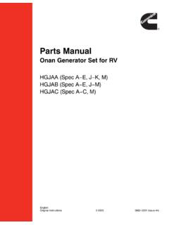
7 If outboard oil is used, drain andrefUl with OMC Type C Lubricant as soonas possible. Lower gear lubricant shouldbe maintained at level of vent plug, anddrained and renewed every 100 hours SYSTEMCARBURETOR. A float type carburetor isused; refer to Fig. OM4-1 for exploded initial setting for slow speed mix-ture needle (25) is ^ATO (2) turns open fromclosed position. Major adjustment shouldbe made with knob (27) removed. Clockwiserotation oi needle leans the mixture. Makefinal adjustment after motor has reachedoperating temperatuie; then reinstall knob(27) with pointer dov/n.
8 High speed mixtureis controlled with a fixed jet (2) and is set the carbur&tor iloat level, first re-move the carburetor; then unbolt and re-move float chamber (3). Invert th carbxire-177 EVINRUDE & JOHNSON 5 & 6 HPOLD OUTBOAF^D MOTORtor body (16) and check the natural positionof float with body inverted. Upper surfaceof float (6) (lower surface with body in-verted) should be level and flush withgasket surface of carburetor body. If it isnot, carefully bend float lever; then checkafter assembly to be sure float does notbind or to Fig.
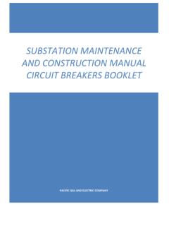
9 OM4-1 when disassemblingor reassembling the carburetor. High speednozzle (9) can be removed with a bladescrewdriver after float chamber (3) is re-moved. Needle valve (10) and seat (11) canbe renewed after removing the float. Renewall gaskets and packing whenever carbure-tor is CONTROL LINKAGE. The speedcontrol lever rotates the magneto armatureplate to advance the timing. The throttlevalve is synchronized with the plate to openthrottle the proper amount as timing synchronize the linkage, remove the topcowl and move speed control lever or grip un-til index mark on cam is aligned with centerof cam follower roller on models prior to 1968as shown in Fig.
10 OM4-2. On 1968 models aligncam follower leading edge with throttle cammark. All slack should be removed from link-Fig. Explodedview of carburelor ondossoeiated Plug2. High-speed Jet3. Float chamber4. Gasket5. Chok knob6. Float7. Float shaft8. Choke shaft9. Nozzle10. Inlet needle11. Needle seat12. Throttle lever13. Follower lever14. Link15. Throttle plate16. Body17. Cam follower18. Spring19. Cam roller20. Retainer21. Bushing22. Throttle shaft23. Spring24. Packing25. Slow speed needle26. Nut27. Adjusting knob28. Choke spring29. Choke plate30. Gasketage, with throttle just ready to open at thistime; if it is not, loosen the two screws secur-ing synchronizing cam to armature plate,then retighten with all slack removed.