Transcription of Example 11 Cast in Place Concrete Cantilever Retaining ...
1 Example 11 - CAST IN Place Concrete Cantilever Retaining WALL==================================== ======================================== =========1 GENERAL INFORMATIONS tarting Element Size Assumptions:Total Footing Width = 70% to 75% of the design heightFooting Thickness = 10% of the design heightToe Width = 10% of design heightMATERIAL PROPERTIESSoil: CDOT Class 1 Backfill-Drained Footing bears on soilSoil unit weight s =kcfAngle of internal friction (backfill) = degWall-backfill friction angle = 2/3 =degCoefficient of active earth pressureKa =(Coulomb)AASHTO Eq.
2 Of passive earth pressureKp =AASHTO Fig. equivalent fluid weightEFW (a) = Ka s =kcf (36 pcf min)BDM equivalent fluid weightEFW (p) = Kp s =kcfSubgrade: for bearing and sliding Nominal design values are typically provided in the project-specific geotechnical soil bearing resistanceqn =ksf Angle of internal friction (subgrade) Sub = deg (for sliding)Wall-subgrade friction angle Sub = 2/3 Sub =deg (for shear key design)Nominal soil sliding coefficient n = tan Sub =AASHTO : CDOT Concrete Class DConcrete compressive strengthf'c =ksiConcrete unit weight c = kcfBridge Rail Type 7 Type 7 bridge rail weightwrail =klfCenter of gravity from wall back =in.
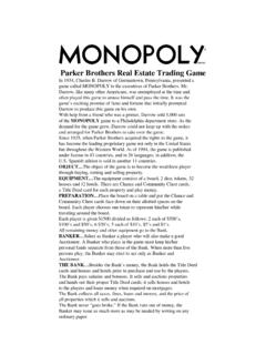
3 (see Bridge Worksheet B-606-7A) Statement:The Retaining wall supports 15'-0" of level roadway embankment measured fromtop of wall to top of footing. The wall will be built adjacent to the roadway shoulder where traffic is 2 the barrier face. The wall stem is 1'-6" wide to accommodate mounting a Type 7 Bridge Rail to thetop of wall. See Figure 11 - CAST-IN- Place Concrete Cantilever Retaining 11 demonstrates design procedures for cast-in- Place Cantilever Retaining walls supported onspread footing in conformance with AASHTO and Section of this BDM.
4 Horizontal earth pressure isapplied based on the Coulomb earth pressure Bridge Design ManualJanuary 2020 Example 11 - CAST IN Place Concrete Cantilever Retaining WALL==================================== ======================================== =========2 RESISTANCE FACTORSWhen not provided in the project-specific geotechnical report, refer to the indicated AASHTO b=AASHTO ( Concrete on soil) T=AASHTO (soil on soil) T s-s=AASHTO pressure ep=AASHTO event EE=AASHTO GEOMETRY INFORMATIONSee Figure HeightH = of Wall ThicknessTTop = of Wall ThicknessTBot = of footingB = of FootingTF = DistanceS = of fill over the toeHTF = Footing embedment 3 + TF = Rail Type 7 HeightHB = Backface to vertical surchargeR = Load Surcharge heighthSur = Table Collision Load (TL-4)PCT =kipAASHTO Table Load DistributionLt = Table of wall to point of collision impact on railhCT = STABILITY CHECKS1.
5 Eccentricity2. Sliding3. Bearing APPLIED LOADSL oads not listed here may be applicable for different design - dead load of structural components and nonstructural attachmentsEH - horizontal earth pressure loadEV - vertical pressure from dead load of earth fillCT - vehicular collision forceLS - live load surchargeNote:The Geotechnical Engineer is responsible for evaluating global stability with consideration for bothfooting width and embedment. the load combinations and factors from AASHTO and BDM Section for all loads actingon the Retaining wall.
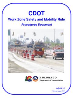
6 Evaluate the Retaining wall for the following: Bridge Design ManualJanuary 2020 Example 11 - CAST IN Place Concrete Cantilever Retaining WALL==================================== ======================================== =========3EV3EV1EV2 LSVLSHEHDC1DC2DC4DC3 FrontFace VB-2eCTAToeHeelRoadway ShoulderBridge RailType7CL Shear Key(when required) 1 - Typical Section RhCTSee Figure 2 for Shear Key InformationCDOT Bridge Design ManualJanuary 2020 Example 11 - CAST IN Place Concrete Cantilever Retaining WALL==================================== ======================================== =========4 Summary of Unfactored Loads and MomentsResolve moments about Point A (see Figure 1 - Typical Section)Load CombinationsEV3 Note: The collision force (CT) is assumed to be distributed over a length of Lt ft.
7 At the point of impactand is also assumed to spread downward to the bottom of the footing at a 45 angle. Conservatively, CTis assumed at the end of the wall where the force distribution occurs in one direction. See Figure 11-20 inSection 11 of this table that follows summarizes the load combinations used for the stability and bearing checks of thewall. To check sliding and eccentricity, load combinations Strength Ia and Extreme Event IIa applyminimum load factors to the vertical loads and maximum load factors to the horizontal loads. To checkbearing, load combinations Strength Ib, Strength IV, and Extreme Event IIb apply maximum load factorsfor both vertical and horizontal loads.
8 (kip-ft.) Arm (ft.) between the Bridge Rail Type 7 and the wall interface is assumed to be adequate to transfer the collision load from the rail through the wall to the (kip/ft.)Vertical component of live load component of horizontal earth pressure Vertical Loads & MomentsStem dead loadDescriptionStem dead loadFooting dead loadBarrier dead loadVertical pressure from dead load of fill on heelVertical pressure from dead load of fill on heelVertical pressure from dead load of fill on toeMH(kip-ft.) Arm (ft.)H(kip/ft.)Horizontal Loads and MomentsHorizontal component of horizontal earth pressureHorizontal component of live load surchargeDescriptionLoad collision /2 sin sin cos cos R CDOT Bridge Design ManualJanuary 2020 Example 11 - CAST IN Place Concrete Cantilever Retaining WALL==================================== ======================================== =========5 The service limit state is used for the crack control check and factored force effect.
9 AASHTO Qi = force effects from loads calculated aboveLoad Modifiers:Ductility D =AASHTO r =Operational Importance I =Load Factors:Summary of Load IIaExtreme IIbCT load is considered with Extreme Event II limit state when checking eccentricity, sliding, and : LSH, LSV, and EHH are not included in Extreme Event IIa or IIb. It is assumed that the horizontal earth pressure is not activated due to the force of the collision deflecting the wall away from the soil mass at the instant of collision. LSVis not applied when analyzing sliding and overturning; rather, it is applied only for load combinationsthat are used to analyze bearing (AASHTO , Figure ).
10 Load CombinationStrength IaStrength IbStrength IVExtreme IIaExtreme IIbService ILoad CombinationStrength IaStrength IbService IApplicationSliding, EV (kip-ft.) Load & MomentH(kip/ft.)MH(kip-ft.) , Strength Load & MomentV(kip/ft.) Crack Control LS_HBearingSliding, CT EH CDOT Bridge Design ManualJanuary 2020 Example 11 - CAST IN Place Concrete Cantilever Retaining WALL==================================== ======================================== =========6 Eccentricity (Overturning) CheckMaximum eccentricity limit:emax =B/3 = Ia: X =( MV - MH) / V =( - ) / = = / 2 - = IIa: X = ( MV - MH) / V =( - ) / = = / 2 - = Resistance CheckVertical stress for wall supported on soil.