Transcription of Experiment 1: Ohm’s Law - IU
1 Kingdom of Saudi Arabia Ministry of Education Islamic University in Madinah Department of Physics Experiment 1: Ohm s Law Objective: To perform an experimental check of Ohm's Law To practice constructing electric circuits Apparatus: Varied value of resistors Power supply Connecting wires Multimeters Rheostat (variable resistance) Theory: In this lab, you will construct a simple circuit using a single known resistance, R. Then you will use an ammeter to measure the current, I, through the resistance and a voltmeter to measure the potential difference, V, across the resistance. With this data, you can check the validity of Ohm's Law (V = IR) in the circuit.
2 Kingdom of Saudi Arabia Ministry of Education Islamic University in Madinah Department of Physics Procedure: 1. Connect the circuit shown below using a fixed resistance R. 2. Set the value of electromotive force into certain voltage (electromotive force). 3. You can get different readings of the current I and voltage V by varying the battery source. 4. Record the value of the current through the resistance and the voltage across it. 5. Repeat step 3 to get at least 6 different readings. 6. Record the data in Table-1 7. Repeat the previous steps for another value of the resistance. Record the data in Table2.
3 Kingdom of Saudi Arabia Ministry of Education Islamic University in Madinah Department of Physics Experiment 1: Ohm s Law Name:_____ ID: _____ Instructor: _____ Section:_____Date:_____ DATA SHEET Table-1 Voltage and current for Resistance R = 1 Current (A) Voltage (V) Resistance R ( ) Average Resistance Ravg Resistance from Slope Kingdom of Saudi Arabia Ministry of Education Islamic University in Madinah Department of Physics 1. Plot a graph of the voltage ( V ) and the current (I), with V on vertical axis and ( I) on horizontal axis. Draw the best straight line fit of the data.
4 2. Determine the slope of the straight line which is the resistance R in this case. Slope = _____ (YOU NEED TO ATTACH A GRAPH PAPER TO THIS DATA SHEET) Table-2 Voltage and current for Resistance R = 10 Current (A) Voltage (V) Resistance R ( ) Average Resistance Ravg Resistance from Slope 3. Plot a graph of the voltage ( V ) and the current (I), with V on vertical axis and ( I) on horizontal axis. Draw the best straight line fit of the data. 4. Determine the slope of the straight line which is the resistance R in this case. Slope = _____ 1 Kingdom of Saudi Arabia Ministry of Education Islamic University in Madinah Department of Physics Experiment No.
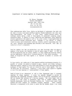
5 2 The rectifier diode Objectives: 1. Ability to recognize diodes in various physical forms. 2. Ability to determine the diode polarity and to understand the need for correct connection. 3. To obtain knowledge of the forward voltage/current characteristic and the conduction voltage for diodes. Apparatus: power source, ammeter, voltmeter, rheostat, resistors, and rectifier diode. Introduction The general from of the current - voltage of a diode is shown in Figure (l). A current flow in the forward direction is very large compared with that in the reverse direction and such a device is very useful as a rectifier. The diode is in the forward direction when an external battery is connected with positive terminal to the (p) region and negative terminal to the region (n).
6 The reverse current through the diode varies greatly with temperature and with the semiconductor materiel used. Fig. 1 V-I characteristics of semiconductor diode 2 Kingdom of Saudi Arabia Ministry of Education Islamic University in Madinah Department of Physics Procedure: 1. Connect the circuit as shown in Figure 2 (a) using silicon diode. 2. Increase the variable DC voltage from zero in steps of ( volts) up to (1 volts), then in step of ( volt) up to (5 volt), and record the voltage across the resistance. 4. Connect the circuit shown in Figure 2 (b) using Si diode. 5. Increase the variable DC voltage from zero in steps of ( volts) up to (2 volt), then in steps of (1 volt) up to (10 volts) and for each step record the current.
7 6. Tabulate your result in a table 1. (a) Forward bias Fig. 2 Forward and reverse bias of diode (b) Reverse bias 3 Kingdom of Saudi Arabia Ministry of Education Islamic University in Madinah Department of Physics Table 1 Forward bias Reverse bias Vs (V) Vr (V) Vd (V) Id (mA) Pd (mW) Vs (V) Vr (V) Vd (V) Id (mA) Pd (mW) 3 4 5 6 7 8 9 10 4 Kingdom of Saudi Arabia Ministry of Education Islamic University in Madinah Department of Physics Experiment No.
8 1 The rectifier diode Name: Date: Physics 106 Section: Instructor s Name: ---------------------------------------- ---------------------------------------- -- Purposes: .. Data and Data Analysis 1. Fill the Table 1, R=.. Forward bias Reverse bias Vs (V) Vr (V) Vd (V) Id (mA) Pd (mW) Vs (V) Vr (V) Vd (V) Id (mA) Pd (mW) 3 4 5 6 7 8 9 5 Kingdom of Saudi Arabia Ministry of Education Islamic University in Madinah Department of Physics 10 2.
9 Plot the diode current Id versus the potential difference across the rectifier diode. 3. From graph find the junction voltage VJ= V 4. Find the slope of curve in each region and calculate the resistance of diode. Slope= A/V, R=1/slope. Forward bias: .. Reverse bias (blocking current) .. 1 Kingdom of Saudi Arabia Ministry of Education Islamic University in Madinah Department of Physics Experiment 2 HALF-WAVE RECTIFIER Purposes: 1. To learn a half-wave rectified sinusoidal voltage. 2. To understand the terms mean value and rout mean square for input and output (rectified) voltage.
10 3. To understand the effect of reservoir capacitor upon the rectified waveform. Apparatus: Electricity & electronics constructor EEC470, basic electricity & electronics kit EEC471-2, multimeter, oscilloscope. 2 Kingdom of Saudi Arabia Ministry of Education Islamic University in Madinah Department of Physics Fig. 1 Experimental setup Introduction The conversion of alternating voltage (changes its direction) to directed voltage. This conversion is called rectification. To achieve the rectification of alternating voltage you must to use some circuit. The simplest one is the half-wave rectifier in which a single diode is used, see Fig.