Transcription of Experiment 2: Kirchhoff’s Law and Superposition …
1 Experiment 2: Kirchhoff s Law andSuperposition Theorem1 Purpose Verify the Kirchhoff s Law and understand what is Kirchhoff s Law. Learn how to measure the branch current by using current plugs. Verify the Superposition theorem and understand Superposition andhomogeneous properties of linear electric Kirchhoff s Law: Kirchhoff s current Law (KCL): The algebraic sum of all the currentsat any node in a circuit equals zero, I= 0. Kirchhoff s voltage Law (KVL): The algebraic sum of all the voltagesaround any closed path in a circuit equals zero, U= Superposition theorem A linear system obeys the principle of Superposition , which states thatwhenever a linear system is excited, or driven, by more than one inde-pendent source of energy, the total response is the sum of the individualresponses.
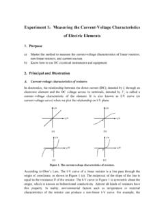
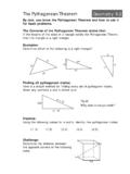
2 An individual response is the result of an independent sourceacting Contents and StepsThe electric circuit of Kirchhoff s Law and the Superposition theorem arethe same as shown in the Fig. Verify the Kirchhoff s Law Set the reference direction of three branch currentI1,I2andI3(Throughthe ammeter socket to set the reference direction of the current, asshown in the Fig. 1(b), red means incoming current and black meansoutgoing current). Turn the switchS1to the left and switchS2to the right, then connectthem with voltage source withUS1= 6 VandUS2= 12V. Insert the current plug(red and black) to the ammeter socket (+ and -).Then insert the current plug to the branch current socket and recordthe current value into Table 1. Measure the voltage value of source and resistances with the voltmeter,and then record them into Table 1.
3 (a)(b)Figure 1: (a) The electric circuit of Kirchhoff s Law and the Superpositiontheorem, (b) the electric circuit of (mA)I2(mA)I3(mA)US1(V)US2(V)Calculated ValueMeasured ValueRelative ErrorUFA(V)UAB(V)UAD(V)UCD(V)UDE(V)Calcu lated ValueMeasured ValueRelative ErrorTable 1: The Measured Data to verify the Kirchhoff s Verify the Superposition theorem The electric circuit as shown in the Fig. 1. Use single voltage sourceUS1(turn the switchS1andS2to the left), measure the branch currentand resistances with ammeter and voltmeter and then record them tothe Table 2. Use the single voltage sourceUS2(turn the switchS1andS2to theright), measure the branch current and resistances with ammeter andvoltmeter and then record them to the Table 2. Use bothUS1andUS2(turn the switchS1to the left andS2to theright), measure the branch current and resistances with ammeter andvoltmeter and then record them to the Table 2.
4 Use the single voltage sourceUS2, but change the voltage to 24V, mea-sure the branch current and resistances with ammeter and voltmeterand then record them to the Table : When using the single voltage source, DO NOT mistake the positiveand negative terminals of the \Measured ItemI1(mA)I2(mA)I3(mA)US1(V)US2(V)Single SourceUS1 Single SourceUS2 SourceUS1andUS2 Single SourceUS2= 24 VUFA(V)UAB(V)UAD(V)UCD(V)UDE(V)Single SourceUS1 Single SourceUS2 SourceUS1andUS2 Single SourceUS2= 24 VTable 2: The measured data of Superposition QuestionsWhen you do the Experiment of the Superposition theorem , how to operatein the Experiment ? Could we just replacing all other independent voltagesources (US1orUS2) with a short circuit?5 Writing Your the calculation (Calculated Value) in Table on the measured value, choose one node as reference node andverify the Kirchhoff s current Law (KCL).
5 On the measured value, choose one node as reference node andverify the Kirchhoff s voltage Law (KVL). on the measured value, verify the Superposition and homogeneityof the linear electric on the measured value, could you calculate the power of resis-tances, are they follow the Superposition theorem ? the question (section 4).4