Transcription of Explanatory Examples for Ductile Detailing of RC Buildings
1 Document No. :: Final Report :: A - Earthquake Codes IITK-GSDMA Project on building Codes Explanatory Examples for Ductile Detailing of RC Buildings by Dr. R. K. Ingle Department of Applied Mechanics Visvesvaraya National Institute of Technology Nagpur Dr. Sudhir K Jain Department of Civil Engineering Indian Institute of Technology Kanpur Kanpur The solved Examples included in this document are based on a draft code being developed under IITK-GSDMA Project on building Codes. The draft code is available at (document number ). This document has been developed through the IITK-GSDMA Project on building Codes.
2 The views and opinions expressed are those of the authors and not necessarily of the GSDMA, the World Bank, IIT Kanpur, or the Bureau of Indian Standards. Comments and feedbacks may please be forwarded to: Prof. Sudhir K Jain, Dept. of Civil Engineering, IIT Kanpur, Kanpur 208016, email: Examples on 13920 Page 3 CONTENTS Sl. No Type of Design Page No. 1. Beam Design of an RC Frame building in Seismic Zone V 4 2.
3 Beam Design of an RC Frame building in Seismic Zone II 15 3. Interior Column Design of an RC Frame building in Seismic Zone V 24 4. Exterior Column Design of an RC Frame building in Seismic Zone V 33 5. Interior Column-Beam Joint Design for Zone V 42 6. Exterior Column -Beam Joint Design for Zone V 48 7. Interior Column-Beam Roof Joint Design for Zone-V 56 8. Exterior Column-Beam Roof Joint Design for Zone V 62 9. Shear Wall Design for a building in Seismic Zone III 69 Examples on 13920 example 1 /Page 4 example 1 - Beam Design of an RC Frame building in Seismic Zone V 1 Problem Statement: A ground plus four storey RC office building of plan dimensions 19 m x 10 m located in seismic zone V on medium soil is considered.
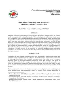
4 It is assumed that there is no parking floor for this building . Seismic analysis is performed using the codal seismic coefficient method. Since the structure is a regular building with a height less than m, as per Clause of IS 1893 (Part 1): 2002, a dynamic analysis need not be carried out. The effect of finite size of joint width ( , rigid offsets at member ends) is not considered in the analysis. However, the effect of shear deformation is considered. Detailed design of the beams along the grid line 2 as per recommendations of IS 13920:1993 has been carried out. Solution: Preliminary Data Plan of the building and sectional elevations of different RC frames are shown in Figures , and The sizes of the beams and columns are given in Table Figure shows beam-loading diagram for dead load and live load, respectively, on an intermediate frame in the transverse direction.
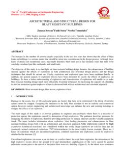
5 C1C1C1C1C1C1C1C1C1C1C2C2C2C2C3C3C3C33444 455123456 ABC Figure : Plan of building (All dimensions in meters) Table :Schedule of member sizes Note: All dimensions in mm. Column Beam C1 300 x 500 RB1, FB1 300 x 600 C2 400 x 400 RB2, FB2 300 x 500 C3 400 x 500 PB1 300 x 400 PB2 300 x 350 Slab thickness: 125 X Y Examples on 13920 example 1 /Page 5 333RB1FB14thRoof3 Figure : Elevation of frame A, B & C Figure.
6 Elevation of transverse frame 1&6 a. Dead Load b. Live Load Figure : Loading diagram for an intermediate frame General Other relevant data are as follows: Grade of concrete: M20 Grade of steel = Fe 415 Live load on roof = kN/m2 (Nil for earthquake) Live load on floors = 3 kN/m2 (25% for earthquake) Roof finish = 1 kN/m2 Floor finish = 1 kN/m2 Brick wall on peripheral beams = 230 mm thick Brick wall on internal beams = 150 mm thick Density of concrete = 25 kN/m3 Density of brick wall including plaster = 20 kN/m3 Load Combinations Load combinations are considered as per IS 456.
7 2000 and are given in Table EQX implies earthquake loading in X direction and EQY stands for earthquake loading in Y direction. The emphasis here is on showing typical calculations for Ductile design and Detailing of Examples on 13920 example 1 /Page 6 building elements subjected to earthquakes. In practice, wind load should also be considered in lieu of earthquake load and the critical of the two load cases should be used for design.
8 Beams parallel to the Y direction are not significantly affected by earthquake force in the X direction (except in case of highly unsymmetrical Buildings ), and vice versa. Beams parallel to Y direction are designed for earthquake loading in Y direction only. Torsion effect is not considered in this example . Table : Load combinations for earthquake loading Load Combination DL LL EQ 1 + - 2 (DL+LL*+EQX) *+ (DL+LL*-EQX) * 4 (DL+LL*+EQY) *+ (DL+LL*-EQY) * 6 (DL+EQX) - + (DL-EQX) - 8 (DL+EQY) - + (DL-EQY)
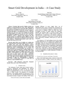
9 - 10 + EQX - + EQX - 12 + EQY - + EQY - *Note: Reduced Live loads are considered as per Clause of IS 1893 (Part 1): 2002, even though it is proposed to drop this clause in the new edition of the Code. For the present case, (live load of 3 kN/m2) 25% of live load is considered for seismic weight calculations. Design of Middle Floor Beam Beam marked ABC in Figure for frame 2 is considered for design.
10 Since the beam consists of two symmetrical spans, calculations need to be performed for one span only. Figure : Beam ABC Member Forces For the beam AB, force resultants for various load cases and load combinations have been obtained from computer analysis and are summarised in Table and Table which show force resultants for different load combinations; with the maximum values to be used for design being underlined. As the beam under consideration is parallel to Y direction, earthquake loads in Y direction are predominant and hence the 13 load combinations of Table reduce to 7 as shown in Table Table.