Transcription of EXPLOSIONPROOF EXM Ex-m Magnet - Schischek
1 EXPLOSIONPROOFENTWURF!!PE12+ 24 +PEPACBDHFCA30 LKIMNKI EXM-650, GH-6 EXM-1300, ..-2000, GH-13/20 A 104 130 B 66 86 C 52 70 D 55 64 E 34 34 F 43 58 G 54 81 H 38 43 I 60 80 K 44 60 L 56 86 M 51 62 N GmbH Germany, Muehlsteig 45, Gewerbegebiet Sued 5, 90579 Langenzenn, Tel. +49 9101 9081-0, Fax +49 9101 9081-77, E-Mail 20-Apr-2016 Subject to change!
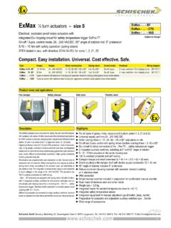
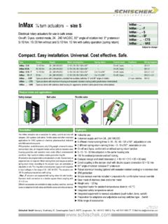
2 Electrical, explosion-proof magnets for fire doors, fire dampers or safety doors and locks. When the supply voltage is cut off, the Magnet looses its retention force and the safety operation is working when using appropriate mechanisms like springs, weights, cranks or similar safety placements provided by the customer. The mag-nets are certified for use in hazardous areas zone 1, 2 (gas, mist, vapour) and zone 21, 22 (dust).Magnetic holder are maintenance free. An inspection is recommended every 6 , explosion-proof magnets for safety applications24 VDC supply voltage, 650 N, 1300 N and 2000 N retention forceEC type-approved in acc. with ATEX directive 2014/ 34/ EU for zone 1, 2, 21, 22, IECEx and DNV-GLEXM Ex-m Magnet For installation, commissioning, use and maintenance all national and international standards, rules and regulations for hazardous Ex-areas must be complied. Every single Magnet has to be connected with an external normal-lag fuse according to its rated current (max.)
3 3 Inominal nach IEC 60127-2 / 1). We recommend stabilised power supply units. The max. AC-ripple must not exceed 20 %. The cable of the Magnet must be installed in a fixed position and protected against mechanical and thermical damage. The temperature class T6 refers to the Magnet . The force of the Magnet can deviate depending on different types of material, dimension and surface of the anchor. A possibly occuring remedy can be avoided by glueing a thin, non-magnetic voltage 24 V DC 10 % (21, ,4 VDC)Ripple max. 20 %Current 45 mA 65 mA 160 mAPower consumption ~ 1 W ~ 1,5 W ~ 3,7 WRetention force Attention: The Magnet power is reduced by increasing AC-ripple ( 20 %). 650 N 1300 N 2000 NElectrical connection ~ 1 m cable PVC non-halogen and silicone free, wire cross section ~ 1 mm , outer equipotential bonding 4 mm finely stranded conductor, 6 mm single-wire Connections in hazardous areas require an Ex-e terminal box !
4 Housing material Steel, plastic (Polycarbonate)Dimensions (L W H) (incl. connectors) ~ 138 66 43 mm ~ 164 86 58 mm ~ 164 86 58 mm Weight ~ 650 g ~ 1950 g ~ 1950 gAmbient temperature +55 C, storage temperature +80 CScope of delivery Electromagnetic holder without anchor plate and mounting materialTechnical data ..-650 ..-1300 ..-2000 Wiring diagramDimensionsSafe areaHazardous area(gn/ye)Ex-e junction boxca. dimension [ mm]1 / GmbH Germany, Muehlsteig 45, Gewerbegebiet Sued 5, 90579 Langenzenn, Tel. +49 9101 9081-0, Fax +49 9101 9081-77, E-Mail ApprobationsSpecial solutions and accessoriesProblem handling / Operational disorder Problem Possible cause Course of action Mains failure Incorrect mains voltage Magnet connected incorrectly Magnet and anchor plate are not in alignment Wrong dimension of Magnet (force insufficient) Check mains, establish mains again Magnet must be repaired by the manufacturer Check connection.
5 If correctly connected Magnet still does not function, it has to be repaired by the manufacturer Check mounting of both parts Choose stronger Magnet 01 Magnet does not provide enough retention force Loose contact in the feed lines Loose contact inside the Magnet Increase of temperature Check and secure connections Magnet must be repaired by the manufacturer Ensure max. ambient temperature not to be exceeded02 Magnet function is occasionally interrupted Remanence Glue remanence foil between Magnet and holder03 Magnet delayed Magnet with 5 m cable (PVC, non-halogen and silicon free)..-15 Magnet with 15 m cable (PVC, non-halogen and silicon free)GH-6 Anchor plate for EXM-650GH-13/20 Anchor plate for EXM-1300 and EXM-2000 ExBox-3P Ex-e terminal boxes for zone 1, 2, 21, 22 EXC-K4 Ex-e terminal boxes with integral fuseEXC-T1 Ex-e push button for manual releaseN1 power supply Input VAC, A, 50/60 Hz / VDC, A Output 24 V DC, max.
6 A1. General informationAll national and international standards, rules and regulations for hazardous Ex-areas must be complied with. In the EU, directive 1999/ 92/ EC is generally applicable as well as other national provisions and regulations. Outside the EU, the corresponding national rules and regulations are , operation and servicing of the equipment may only be carried out by especially trained personnel, who are experienced with the dangers and have also read and understood the instructions. For electrical installations inspection and maintenance, EN/ IEC 60079-17 can be assembly may be carried out only by skilled electrical personnel in accordance with IEC/ EN 60079-14 and such skilled personnel, who comply with the guidelines prevalent in the respective country. It is mandatory that only especially trained personnel should use this equipment. Customers may not open or alter structurally the Magnet (loss of explosion protection and loss of guarantee claims).
7 Proper transportation, storage, installation (within the specified environmental conditions) and maintenance, are absolutely necessary for precise and safe the equipment show damage that leaves the assumption that safe use is not possible the equipment must not remain in operation and must be explosion-proof equipment is operated in aggressive surroundings ( in the chemical industry, offshore, onshore) it should be cleared that casing or parts of such are suitable for the work environment. Each piece of equipment may only be used for the respective purpose. Using the equipment for not specified purposes may affect the guaranteed function. In case of ambiguities or for information that hasn t been provided please contact your dealer or our MountingDuring mounting please be aware that the anchor plate and the Magnet must be in alignment. Improper installation will lead to breakdowns and a reduction of the retention force.
8 It is crucial to protect this equipment from impacts and vibrations that are stronger than the nominal force of the magnets (even for a short time). 3. Electrical ConnectionElectrical installation and commisioning of explosion-proof equipment must be performed according to the respective country s rules and regulations for installation of electrical equipment in explosive areas. National differences are possible as well. Electrical cables must be installed in a fixed position and protected against mechanical and thermical damage. Connect potential earth. Electrical connections inside the Ex area are only allowed to be done by means of an explosion-proof junction box. During this procedure you must take into account that the cable glands must be tightened completely by the contractor. The terminal box must not be opened when the voltage is on !The Magnet s electrical connections must always be made with the current switched off.
9 The connection must be executed according to the wiring operating voltage of the Magnet is 24 VDC 10 % and must not be exceeded by the available supply voltage provided by the customer. The Schischek Company does not accept damaged magnets as a warranty claim caused by excess CommissioningBefore commissioning the junction box s cover must be closed and the fixing screws tightened. The Magnet should show no sign of mechanical damage (Ex protection). Before you switch on the equipment you have to ensure that the impressed voltage is 24 VDC 10 %. The commissioning starts with the inspection of the installation ( Magnet and anchor plate are aligned) and the wiring, followed by a function , all Ex relevant components in the hazardous area between the Magnet and the switch gear, should be examined to ensure that no damage has been done and the installation is DecommissioningBefore switching off, consider the effects on the system as well as on the following devices.
10 Disconnect the main connection before starting mechanical dismantling. The terminal box must be free of MaintenanceThe Magnet must not be opened by the operator. Please exchange damaged magnets or terminal boxes for new ones immediately or have them overhauled by Schischek GmbH. Important information for installation and operationATEX directive 2014/ 34/ EUEC type-approved EPS 14 ATEX 1 713 XIECEx certified IECEx EPS for gas II 2 G Ex mb IIC T6 GbApproval for dust II 2 D Ex tb IIIC T80 C Db IP65CE identification CE No 0158 EMC directive 2014/ 30/ EULow voltage directive 2014/ 35/ EUEnclosure protection IP65 nach EN 60529 DNV GL type-approved TAF0000042, F-AMC2 / 2