Transcription of EXPLOSIONPROOF InMax ¼ turn actuators – size M …
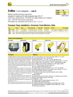
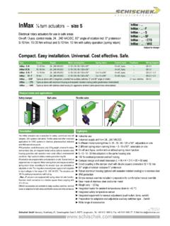
1 EXPLOSIONPROOFInMax - .. InMax - .. - FInMax - .. - SInMax - .. - SFInMax - .. - CTMInMax - .. - GmbH Germany, Muehlsteig 45, Gewerbegebiet Sued 5, 90579 Langenzenn, Tel. +49 9101 9081-0, Fax +49 9101 9081-77, E-Mail 20-Aug-2018 Subject to change!Compact. Easy installation. Universal. Cost effective. views and applicationsDescriptionHighlightsSafety damperBall valveThrottle valveElectrical rotary actuators for use in safe areasOn-off / 3-pos. control mode, VAC/DC, 95 angle of rotation incl. 5 pretension50 / 75 100 150 Nm without and 30 50 60 Nm with safety operation (spring return)Type Torque Supply Motor running time Spring return Control mode Feedback Wiring diagramInMax- 50 / 75 Nm VAC/DC 40 / 60 / 90 / 120 / 150 s / 90 On-off, 3-pos. SB 100 100 Nm VAC/DC 40 / 60 / 90 / 120 / 150 s / 90 On-off, 3-pos.
2 SB 150 150 Nm VAC/DC 40 / 60 / 90 / 120 s / 90 On-off, 3-pos. SB 30 - F 30 Nm VAC/DC 40 / 60 / 90 / 120 / 150 s / 90 ~ 20 s/ 90 On-off, 3-pos. SB + 50 - F 50 Nm VAC/DC 40 / 60 / 90 / 120 / 150 s / 90 ~ 20 s/ 90 On-off, 3-pos. SB + 60 - F 60 Nm VAC/DC 40 / 60 / 90 / 120 s / 90 ~ 20 s/ 90 On-off, 3-pos. SB + .. - S/SF Types as above with 2 integrated, potential free auxiliary switches, 5 and 85 angle of rotation 2 aux. switches SB .. - CTM Types as above with aluminium housing and seawater resistant coating (cable glands brass nickel-plated) InMax - .. - VAM Types as above with stainless steel housing for aggressive ambient (cable glands brass nickel-plated) InMax turn actuators size M Industrial use Universal supply unit from VAC/DC Different motor running times 40 60 90 120 150 s/ 90 , adjustable on site Spring return running time ~ 20 s/ 90 On-off and 3-pos.
3 Control with or without spring return function 30 50 60 75 100 150 Nm actuators in the same housing size 100 % overload protected Compact design and small dimension (L W H ~ 288 149 116 mm) Direct coupling to the damper shaft with double square connection 16 16 mm 95 angle of rotation inclusive 5 pretension Robust aluminium housing (optional with seawater resistant coating)or in stainless steel IP67 protection Simple manual override included + preparation for comfortable manual override Gear made of stainless steel and sinter metal Weight only ~ 9,5 kg Integrated heater for ambient temperatures down to 40 C Integrated safety temperature sensor Integrated equipment for manual adjustment (push button, lamp, switch) Preparation for adaptable and adjustable auxiliary switches type ..Switch Wide range of accessoriesThe InMax actuators are a revolution for safety, control and shut-off dampers, ball valves, throttle valves and other motorized applications for HVAC systems in chemical, pharmaceutical, industrial and offshore/onshore protection, small dimensions, only 9,5 kg weight, universal functions and technical data, an integrated heater and an optional stainless steel housing guarantee safe operation even under difficult environmental conditions.
4 High quality brushless motors guarantee long actuators are programmable and adjustable on site. Special tools or equipment are not required. Motor running times and torques are selectable or adjustable on site. The integrated universal power supply is self adaptable to input voltages in the range of VAC/DC. The actuators are 100 % overload actuators are equipped with spring return fail safe function. Standard shaft connection is a double square direct coupling with 16 16 mm. Different accessories are available to adapt auxiliary switches, terminal boxes or adaptions for ball valves and throttle valves and other armatures. 1 / GmbH Germany, Muehlsteig 45, Gewerbegebiet Sued 5, 90579 Langenzenn, Tel. +49 9101 9081-0, Fax +49 9101 9081-77, E-Mail option .. -CTMA pprobationsSpecial solutions and accessoriesTechnical data InMax - InMax - 100 InMax - 150 InMax - 30 -F InMax - 50 -F InMax - 60-FTorque motor (min.)
5 50 / 75 Nm selectable 100 Nm 150 Nm 30 Nm 50 Nm 60 NmTorque spring (F) min. 30 Nm min. 50 Nm min. 60 NmTorque blockade In blockade and end positions torques are higher than above specified torques for motor and of external load Upon spring return the external load should be max. 80 % of torque spring (F), but min. 10 NmSupply voltage / frequency VAC/DC, 10 %, self adaptable, frequency Hz 20 %Power consumption max. starting currents see Extra information (in acc. with voltage, I start >> I rated ), approx. 5 W holding power, approx. 16 W for heaterProtection class Class I (grounded)Angle of rotation and indication 95 incl. ~ 5 pretension, mechanical value indicationWorking direction Selectable by left/right mounting to the damper/valve shaftMotor running times [s/ 90 ] 40/ 60/ 90/ 120/ 150 40/ 60/ 90/ 120/ 150 40/ 60/ 90/ 120 40/ 60/ 90/ 120/ 150 40/ 60/ 90/ 120/ 150 40/ 60/ 90/ 120 Motor Brushless DC motor Control mode On-off and 3-pos.
6 In acc. with wiring, selectable on site Spring return (F) spring return upon voltage interruptionSpring return response time up to 1 sec. after voltage interruptionSpring return running time (F) ~ 20 s/ 90 Safety operations at 20 sec. (F) min. 10,000 acc. to construction of damper and ambientAuxiliary switches ..-S, ..-SF 2 integrated auxiliary switches, switching at 5 and 85 angle of rotation, potential free. Grid fuse-protection is recommended ! Umax/ Imax AC = 250 V/ 5 A; Umin AC/DC = 5 V; After one-time operation with U > 24 V AC/DC or I > 100 mA: Umin AC/DC = 12 V Umax/ Imax DC = 48 V/ 1 A; Imin AC/DC = 5 mA; Imin AC/DC = 100 mAAxle of the actuator Double square 16 16 mm, direct coupling, 100 % overload protectedElectrical connection Cable ~ 1 m, wire cross section mm , equipotential bonding 4 mm.
7 Connections require a terminal box !Diameter of cable ~ mm ~ mm ~ mm ~ mm ~ mm ~ mm 2 flying leads at each type ..-S and ..-SF (~ .. + mm) Cable gland M16 mmManual override Use delivered socket wrench, max. 4 Nm Heater Integrated, controlled heater for ambient temperature down to 40 CHousing material Aluminium die-cast housing, coated. Optional with seawater resistant coating (..-CTM) or stainless steel housing, No / UNS-J92900 / similar AISI 316Nb (..-VAM)Dimensions (L W H) ~ 288 149 116 mm, for diagrams see Extra informationWeight ~ kg aluminium housing, stainless steel ~ 15 kgAmbients Storage temperature +70 C, working temperature +50 CHumidity % rH, non condensingOperation mode 80 % of ED are permitted (ED = duty cycle)Maintenance Maintenance free relative to function, maintenance must comply with regional standards, rules and regulations Wiring diagrams SB SB SB SB / SB / SB / Scope of delivery Actuator with 1 m cable, 4 screws M8 140 mm, 4 nuts M8, Allen key for simple manual overrideParameter at delivery 50 Nm, 90 s/ 90 100 Nm, 90 s/ 90 150 Nm, 90 s/ 90 30 Nm, 90 s/ 90 50 Nm, 90 s/ 90 60 Nm, 90 s/ 90.
8 -CTM Types in aluminium housing with seawater resistant coating, parts Types in stainless steel housing, parts Terminal boxesMKK-M Mounting bracket for boxes type .. directly on actuatorInSwitch 2 external aux. switches, adjustableHV-MK Comfortable manual override for ..Max actuators size MAR-16-xx Reduction part for 16 mm square connection to 14 or 12 mm shaftsKit-S8 Cable glands nickel-platedAdaptions for dampers and valves on request Ambient temperature up to +60 C, VAC/ DC, 25 % EDInMax-50-SF-S9 Without thermal fuse, aux. switches at 0 and 80 angle of rotationCE identification CEEMC directive 2014/ 30/ EULow voltage directive 2014/ 35/ EUEnclosure protection IP67 in acc. with EN 60529 EAC TC N RU Д-DE.АВ45.В.586072 / 4 EXPLOSIONPROOF !! InMax - InMax - 100 InMax - 150 InMax - 30 -F InMax - 50 -F InMax - 60 -F 50 Nm100 Nm150 Nm30 Nm50 Nm60 Nm 75 Nm 40 s / 90 60 s / 90 90 s / 90 120 s / 90 150 s / 90 00010203040506070809 InBoxaaabbb+~+~+~+~ ~ ~ ~ ~PEPEPEPE1111222233334444 PAPAPAPA142356< 5 > 85 U < 90 V AC/DC 2 AT 10 ATU > 90 V AC/DC 5 AT 10 GmbH Germany, Muehlsteig 45, Gewerbegebiet Sued 5, 90579 Langenzenn, Tel.
9 +49 9101 9081-0, Fax +49 9101 9081-77, E-Mail option .. -CTME lectrical connectionParameters, adjustments and failure indicationParameter selectionFunctions, adjustments and parametersTypeRunning timesPosition of switch (S)TorquesExample: parameter: Torque 75 NmMotor running time 90 s/ 90 Result:Switch position 07 All actuators are equipped with a universal supply unit working at a voltage range from VAC/DC. The supply unit is self adjusting to the connected voltage ! The safety operation of the spring return function works if the supply voltage is cut. For electrical connection a terminal box is required ( InBox). An over-current protection fuse < 10 A has to be provided by installer. Note: the initial current is appr. 2 A for 1 auxiliary switches signal the rotation angle s position. Umin and Imin change once the switches were operated with higher voltage or * VAC/DC 10 %* electrical wiring see diagramsOn-off / 3-pos.
10 SB / 3-pos. SB (1 wire) SB of integrated auxiliary switches SB diagram InMax - .. (without spring return)Wiring diagram InMax - .. -F (with spring return)Wiring diagram InMax - .. -S and .. -SFAttention!At 1-wire control mode the heater does not work in case of open contact. Wiring of actuator acc. to type and application see diagrams aboveWiring of the integrated, potential free auxiliary VAC/ VAC/ VAC/ VAC/ DCAttentionDuring commissioning apply a self adjustment drive. Regard duty cycle at motor running times !Never use spring return actuators without external switches * see Technical dataIntegrated auxiliary switches, Grid fuse-protection recommended. min. ) Self adjustment of angle of rotation Turn switch (S) to position 02 (low torque) or 07 (high torque). Press button (T) for a minimum of 3 seconds. The actuator drives to both end positions and detects the blocking positions.