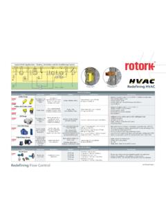
Transcription of ExRun Valve actuators with continuous control - …
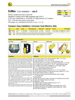
1 ENTWURFEXPLOSIONPROOFExRun - .. - YExRun - .. - GmbH Germany, Muehlsteig 45, Gewerbegebiet Sued 5, 90579 Langenzenn, Tel. +49 9101 9081-0, Fax +49 9101 9081-77, E-Mail 9-May-2017 Subject to change!Compact. Easy installation. Universal. Cost effective. views and applicationsDescriptionHighlightsElectri cal, explosion proof linear actuators 500 N to 10,000 VAC/ DC, mm adjustable strokeATEX tested in acc. with directive 2014/ 34/ EU for zone 1, 2, 21, 22 ExRun Valve actuators with continuous controlType Force Supply Motor running time control mode Feedback Wiring diagramExRun- - Y 0,5 kN / 1,0 kN VAC/ DC 2 / 3 / 6 / 9 / 12 s / mm VDC, mA VDC, mA SB - Y 2,5 kN / 5,0 kN VAC/ DC 2 / 3 / 6 / 9 / 12 s / mm VDC, mA VDC, mA SB Y 7,5 kN / 10,0 kN VAC/ DC 4 / 6 / 9 / 12 / 15 s / mm VDC, mA VDC, mA SB.
2 - CTS Types as above with aluminium housing and seawater resistant coating (exterior parts in stainless steel, cable glands brass nickel-plated)..RunSide viewBack view with terminal mounted on valveCompact bodyExRun Valve actuators are the new generation of electrical, explosion proof adjustment and control valves and other motorized applications for HVAC systems in chemical, pharmaceutical, industrial and offshore/onshore plants, for use in Ex-areas zone 1, 2 (gas) and zone 21, 22 (dust). Highest protection class and IP66 protection, compact dimensions, little weight, universal functions and technical data and an integrated heater guarantee safe operation even under difficult environmental conditions. High quality brushless motors guarantee long actuators are programmable and adjustable on site.
3 Special tools or equipment are not required. Motor running times and forces, accord-ing to the actuator type, are selectable or adjustable on site. The inte-grated universal power supply is self adaptable to input voltages in the range of VAC/DC. The actuators are 100 % overload protected and self modular concept offers the possibility to mount adjustable end switches for signalization. For all type of gas, mists, vapours and dust for use in zone 1, 2, 21 and 22 Universal supply unit from VAC/DC Integrated junction box Motor running times 2 3 4 6 9 12 15 s/ mm, acc. to type continuous control , feedback signals VDC and mA Reverse function Forces 500 1000 2500 5000 7500 10000 N, acc. to type Feedback gear unit, adjustable in steps 10 / 20 / 30 / 60 mm Mechanical stroke limitation, mm stroke adjustable 100 % overload protected and self locking Compact design and small dimensions Robust aluminium housing (optional with seawater resistant coating) IP66 protection Manual override included + preparation for comfortable manual override Weight ~ 7 kg Integral safety temperature sensor Status indication by LED1 / GmbH Germany, Muehlsteig 45, Gewerbegebiet Sued 5, 90579 Langenzenn, Tel.
4 +49 9101 9081-0, Fax +49 9101 9081-77, E-Mail option .. -CTST echnical data ExRun - -Y ExRun - -Y ExRun - -YApprobationsSpecial solutions and Types in aluminium housing with seawater resistant coating, parts nickel-platedExSwitch-R-L External linear aux. switches, 2 separately adjustable contacts, for mounting on ..Run s spindle in zone 1, 2, 21, 22 ExBox/SW Ex-e terminal box for aux. switches ..Switch-R-LMKK-S Mounting bracket, V2A, for terminal boxes .. directly on actuatorHV-R Retrofit manual override for ..Run actuatorsGMB-1 Rubber bellow, 60 mmWS-R Weather shield in stainless steel Adaptions For fittings and manufacturers on : at loss of control signal the rod stops and remains in current 5 kN: Ambient temp.
5 Up to +60 C (T4), VAC/ DC, 25 % EDForce (nominal) 0,5 / 1,0 kN selectable 2,5 / 5,0 kN selectable 7,5 / 10 kN selectableBlocking force in end position * ~ 1,2 / 1,8 kN ~ 4 / 7,5 kN ~ 10 / 12,5 kNSupply voltage / frequency VAC/ DC, 10 %, self adaptable, frequency Hz 20 %Power consumption max. starting currents see Extra information (in acc. with voltage, I start >> I rated ), 2 A inrush currentProtection class Class I (grounded)Heater consumption ~ 16 W (motor is not running at this moment), turns on automatically at low ambient temperaturesStroke mm (adjustable)Motor running times (selectable) 2 / 3 / 6 / 9 / 12 s / mm 2 / 3 / 6 / 9 / 12 s / mm 4 / 6 / 9 / 12 / 15 s / mmMotor Brushless DC motorControl mode Y VDC, mA in acc. with wiring, selectable on site.
6 Galvanic separation between supply and Y-signalFeedback signal U VDC, mA in acc. with wiring, selectable on site, both signals are available at the same timeResistance of Y and U signals Input signal: YU VDC at 10 k , YI mA at 100 Feedback signal: UU VDC at , UI mA at Reverse function Bridge between terminals 3 4 (signal line) effects a reverse function of input and output signals (Y and U)Compulsion control In modulation mode an On-off compulsion control can be performed by external connection / wiring independently from the modulating signalAdjustment of Y und U In case of external mechanical limitation of operating displacement, it is possible to perform an adjustment drive started by touching the buttonElectrical connection Ex-e junction box incl.
7 Terminals 0, mm Cable gland M20 1,5 mm, II2GD Ex-e approved, cable diameter mmManual override Change from motor to hand mode with red turn-switch on the side, use Allen key s top side, max. 5 NmHousing material Aluminium die-cast housing, coated. Optional with seawater resistant coating (..-CTS)Dimensions (L W H) ~ 208 115 254 mm (types 5 kN), ~ 208 115 298 mm (types 7,5 kN), for diagrams see Extra informationWeight ~ 7 kg (standard version without adaption)Ambients Storage temperature +70 C, working temperature +40 C at T6 and +50 C at T5 Ambient temperature 30 C 20 C: reduced forces approx. 60 % of rated value, 5 kN 3 kN (max.). Avoid icing !Humidity % rH, non condensingOperation mode S3 50 % ED intermittent mode (ED = duty cycle), max.
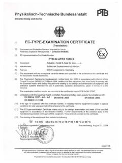
8 300 operating cycles / hAccuracy mechanically < 1 mm stroke (hysteresis)Accuracy electrically ~ 200 steps acc. to stroke adjustment Gear belt adjustment (page 4)Wiring diagrams SB For adjusting control and feedback signal UV / UmA acc. to stroke setting please note page 4 Scope of delivery Actuator with integrated junction box, Allen key for manual overrideParameter at delivery 500 N, 6 s/ mm 2,5 kN, 6 s/ mm 7,5 kN, 9 s/ mm* Uncertainty of measurement 10 %. Note also the chapter on dimensioning!ATEX directive 2014/ 34/ EUEC type-approved PTB 09 ATEX 1016 XIECEx certified IECEx PTB for gas II 2 (1) G Ex de [ia] IIC T6, T5 Types ..-CTS II 2 (1) G Ex de [ia] IIB T6, T5 Approval for dust II 2 (1) D Ex tD [iaD] A21 IP66 T80, T95 CCE identification CE No 0158 EMC directive 2014/ 30/ EULow voltage directive 2014/ 35/ EUEnclosure protection IP66 in acc.
9 With EN 60529 EAC No ТС RU С-DE.ГБ08.В.015102 / 4 explosionproof !! ExRun - ExRun - ExRun - 500 N N N N 2 s / mm 3 s / mm 6 s / mm 9 s / mm 12 s / mm 4 s / mm 6 s / mm 9 s / mm 12 s / mm 15 s / mm 0001020304050607080905060708090001020304 112233445 VAC/ DC+~ ~ GmbH Germany, Muehlsteig 45, Gewerbegebiet Sued 5, 90579 Langenzenn, Tel. +49 9101 9081-0, Fax +49 9101 9081-77, E-Mail option .. -CTSE lectrical connectionParameters, adjustments and failure indicationParameter selectionFunctions, adjustments and parametersTypeRunning timesRunning timesPosition of switch SPosition of switchForcesForcesExample: parameter: Force NRunning time 6 s/ mmResult:Switch position 07A) Self adjustment of stroke: Push button (T) for minimum 3 seconds.
10 The actuator will drive into both end positions to be adjusted. LED indicates GREEN. Adjustment drive can be applied in any switch (S) ) Selection of running time and force: Put switch (S) into the correct selected position in acc. to above table. The selected parameter will work at next operation of the actuator. Adjustment can be done even without supply voltage. If supply voltage is available turn switch only if actuator is not ) Force control : a closed, b open = rod goes in b closed, a open = rod goes outa and b closed = motor doesn t work, no function a and b opened = motor doesn t work, no function 1. Switch off the power2. Open cover of junction box3. Put cable through cable gland into junction box 4. Strip wires approx. 7 mm5. Connect wires acc.