Transcription of Extending Orifice Flow Data - okcc.com
1 Extending Orifice Flow BOX Q TRUMBULL, CT 06611 CT PHONE (203) 261-6711 TOLL FREE PHONE (800) 533-3285 FAX (203) 261-8331 O'KEEFE CONTROLS CO. 2003 ALL RIGHTS RESERVED e-mail website is the CV for the Orifice withdiameter = Other Orifice Sizes Air FlowTo calculate the required diameter of anorifice that is not included in the charts onpages 20-22 use the following equations are based on data taken forthe size no. 60 (.060" dia.) Orifice . QL dL = .060 Q60 in. :dL = diameter of the unknown = flow through the unknown = flow from chart on pages : ( data from page 21)At supply pressure of 50 psig and outlet atstandard conditions,Q60 = SLPM (from chart)Let:QL = 600 SLPM @ 50 psig 600 dL = .060 = .157 in. dia. Water FlowUsing the CV method for liquid flow, andusing measured CV data we can derive thefollowing formula to calculate requiredorifice QL dL = PWhere:dL = diameter of unknown Orifice (in.)
2 QL = required flow (gpm)EXAMPLE:Flow rate required =.5 GPM @ P = psi1 .5 dL = 1 = .149" , to obtain the CV QL .5 CVL = P = 1 = .5 Low Pressure ExtrapolationTo calculate flow rates at pressures lowerthan those on the charts, use the followingformula. QLP = Q5 PLP2 + PLP = Flow at the low pressure (below 5 psig.)Q5 = Chart flow reading at 5 = Low pressure in :To calculate the flow at a supply pressureof psig. for the No. 16 metal = + (.5) = SCFH (from chart)3. Temperature Effects Air FlowThe flow of gases through an Orifice var-ies inversely as the absolute the gas temperature rises and the gasdensity decreases, the mass flow rate extend the chart data on pages 20-22for air flow, use the following formula. TS QT = QS TTWhere:TS = standard absolute temperature R ( R = 460 + F).
3 TT = non standard absolute temperature = flow from chart at 70 F = 530 = flow at a different :At 70 F and an inlet pressure of 25 psigthe No. 60 (.060" dia.) Orifice has a flowrate of SLPM (see page 21). Undersimilar conditions, the air flow rate at300 F is530 QT = 760 = SLPM1. Specific Gravity Other GasesTo convert air flow from chart to anothergas (gas) = Flow (air) / (gas)EXAMPLE:To obtain flow rate for helium when airflow is 5 SCFHFlow (Helium) = Flow (air) / .138 = 5 / .371 = = specific gravity of gas relative to = .138 for Helium2. Pressure Air Flow High Pressure ExtrapolationTo calculate flow rates at pressures higherthan those on the charts, use the follow-ing formula. QHP = Q80 x PHP + = Flow at elevated pressure (above 80 psig.).Q80 = Chart flow reading at 80 = Elevated pressure in :To calculate the flow for the No.
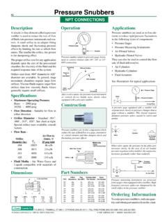
4 16 metalorifice at 150 psig supply = x 150 + = SCFH (from chart) SpecificChart 1 Specific gravity relative to air @ 70 F, psiaNote 2 To obtain the flow of gases other than air,multiply the air flow values on the charts on pages20, 21 and 22 by the chart multiplier. Conversion FactorsA. Gas FlowSCFH - standard cu. ft. per hourSLPM - standard liters per minuteSCCM - standard cu. cm. per minuteSCFH x .472 = SLPMSCFH x 472 = SCCMSLPM x 1000 = SCCMEXAMPLE:5 SCFH x .472 = SLPMB. Liquid FlowGPM - gallons per minuteLPM - liters per minuteCCM - cubic centimeters per minuteCFH - cubic feet per hourCFM - cubic feet per minuteGPM x = LPMGPM x 3785 = CCMGPM x .1337 = CFMGPM x = CFHCCM x .001 = LPMEXAMPLE:25 GPM x = LPMC. Pressure Gases or LiquidsPSIG - pounds per sq. in. gageKg/CM2 - kilograms per sq. cmKPA - kilo pascalsBar - unit of pressure equal to 1 - pressure produced by 1" H2 OPSIG x.
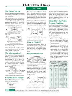
5 0703 = Kg/CM2 PSIG x = KPAPSIG x .0689 = BarsPSIG x = In. H2 OEXAMPLE:25 psig x = KPAT echnical ConsiderationsMISCELLANEOUSL iquid Flow Cv MethodA. WaterThe Cv method of rating flow capacity ofvarious devices employs empirical databased on water flow. The basic formula forwater flow is Q = Cv PTest ProceduresA. Rotameters - Gas FlowRotameters for measurement of air or othergas flows must be used for the conditionsfor which they are calibrated. Typically theyare calibrated for the following: Air Flow Outlet Conditions - psig @ 70 FRotameters can be calibrated for other gasflows or other outlet pressure also provide graphs or tablesfor correction of measured data when con-ditions vary from the calibration using rotameters calibrated for stan-dard outlet conditions use the test proceduresshown Supply PressureVacuum SourceB.
6 Mass Flowmeters - Gas FlowMass flowmeters are generally insensitiveto gas pressure or barometric pressure con-ditions. Consequently their location in thetest circuit is not critical. Consult your in-strument manufacturer for recommendedtest Instrument Accuracy - Gas FlowThe three variables to be measured in gasflow applications are: Pressure Temperature Flow RateThe accuracy of the flow measurement of agas through an Orifice is limited by the com-bined accuracy of the instruments used inthe measurement. Expected accuracy of agas flow measurement is generally in therange of 1 to 20%. 1% accuracy can only beachieved with high quality = flow in GPM P = pressure differential in psiCv = flow factor For a flow of 1 gpm at P = 1, the Cv = 1To obtain the water flow rate through preci-sion orifices use the above equation and ob-tain the Cv value from the charts on pages23, :Size Number 100 (.)
7 100" dia.) has a Cv = .23 For a 25 psig pressure differential:Q = Cv P = .23 25 = GPMS elected flow data is also presented on pages23, 24. The chart data assumes flooded con-ditions on both sides of the Orifice . This isparticularly important for orifices less " diameter because of surface Other LiquidsFor liquids other than water, the equationbecomes:Q = Cv = Specific gravity of the liquid(The specific gravity of water is )To obtain the flow rate of an oil with =.85, use the above equation and obtain theCv value from the charts on pages 20, 21, : Size number 100 (.100" dia.)has a Cv = .23 For a 25 psig pressure differential:Q = Cv P = .23 25 = BOX Q TRUMBULL, CT 06611 CT PHONE (203) 261-6711 TOLL FREE PHONE (800) 533-3285 FAX (203) 261-8331 O'KEEFE CONTROLS CO. 2003 ALL RIGHTS RESERVED e-mail website Gravity of VariousLiquids Relative to Water @ 60 FAlcohol, P20 BOX Q TRUMBULL, CONNECTICUT 06611 CT PHONE (203) 261-6711 TOLL FREE PHONE (800) 533-3285 FAX (203) 261-8331 O'KEEFE CONTROLS CO.
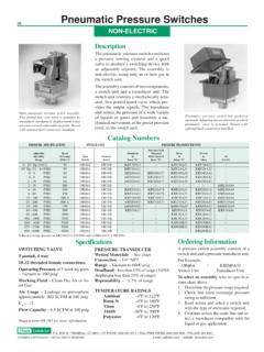
8 2003 ALL RIGHTS RESERVED e-mail website Orifice Air Flow Pressure psigChoked FlowVacuum LevelIn. Pressure psigChoked 5255 216 237250 286 286 160172185 203216242256275305 248 278 292316 347381405464 239265 280314331356392 483532566 648 214233269301320347375400445 473 244 267307343362394428458 509 538 604 638693 763 839 8921021112580931031101191271311371451672 10231 273298343384405443481513570 604 6787167788569431000114612639010611512213 2141146151161185231256303331379424447489 5325686316707507928609471042110612671398 100114126135146156164167177203254282 331 362 415 468496 540587 627697 739 831875 LevelIn. Conditions 70 F, psiaSCFH Standard Cu.
9 Ft. Per HourAbove data obtained with Type B restrictor. Flow rates for other metal restrictors areSLPM Standard Liters Per Minuteessentially the same as for Type B. Above data supercedes previous Orifice Air Flow Pressure psigChoked FlowVacuum LevelIn. Pressure psigChoked 5255 215227247272 223250264 209227 242269285320338367404445472541 LevelIn. Conditions 70 F, psiaSCFH Standard Cu. Ft. Per HourAbove data obtained with Type B restrictor. Flow rates for other metal restrictors areSLPM Standard Liters Per Minuteessentially the same as for Type B. Above data supercedes previous publications. BOX Q TRUMBULL, CONNECTICUT 06611 CT PHONE (203) 261-6711 TOLL FREE PHONE (800) 533-3285 FAX (203) 261-8331 O'KEEFE CONTROLS CO.
10 2003 ALL RIGHTS RESERVED e-mail website BOX Q TRUMBULL, CONNECTICUT 06611 CT PHONE (203) 261-6711 TOLL FREE PHONE (800) 533-3285 FAX (203) 261-8331 O'KEEFE CONTROLS CO. 2003 ALL RIGHTS RESERVED e-mail website Orifice Air Flow Pressure psigChoked FlowSupply Pressure psigChoked LevelIn.