Transcription of EZ TM LZ Series Bottle Filling Stations & Coolers TM
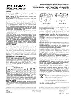
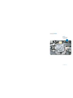
1 Page 11000001731 (Rev. A- 3/14)EZSDWS*1F EZS8WS*1F, 2F, 3F LZSDWS*1F, 2F, 3F LZS8WS*1F, 2F, 3 FEZ & LZ Stations de Remplissage de Bouteille S rie et RefroidisseursEZ & LZ Serie Botella Bombas y EnfriadoresEZ & LZ Series Bottle Filling Stations & CoolersINSTALLATION, CARE & USE MANUALTMTMTMM anual de Instalaci n, Cuidado y Utilizaci nManuel d installation/ 704 937 2673 129 Oak Park Dr., Unit A, Mooresville, NC 28115 Page 2 EZSDWS*1F EZS8WS*1F, 2F 3F LZSDWS*1F, 2F, 3F LZS8WS*1F, 2F, 3F1000001731 (Rev. A - 3/14) Uses HFC-134A refrigerant Usa refrigerante HFC-134 AUtilise du fluide frigorig ne HFC-134A 818151 See Fig. 12122116132042119 See Fig. 32312 141236 Fig. 1191719527 Pictured is unit only without Bottle 704 937 2673 129 Oak Park Dr., Unit A, Mooresville, NC 28115 Page 31000001731 (Rev.)
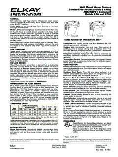
2 A- 3/14)EZSDWS*1F EZS8WS*1F, 2F, 3F LZSDWS*1F, 2F, 3F LZS8WS*1F, 2F, 3 FLCFEAB7/16" X 3/4" OBROUND(11mm X 19mm) HOLES (6)CHANGER BRACKETDE9/32" O HOLES(7mm) (12)7"178mm7"178mm17 7/8"454mm6 3/8"162mm6 3/8"162mm2"51mm2"51mm5 3/4"146mm13 15/16"354mm17 7/16"443mm19"483mm28 13/16"732mm51 9/16"1310mm18 7/8"479mm12 1/2"318mm31 5/16"796mmRIMHEIGHT32 7/8"835mmORIFICEHEIGHTFINISHED FLOOR21 7/8"556mm2"51mm3 7/8"98mm7"178mm7"178mm28 13/16"732mm2"51mm2 7/8"73mm15"381mm27"686mmADAREQUIREMENT8 1/16"205mm19"483mm3 9/16"90mm5 7/8"150mm3"77mm2"51mmLEGEND/LEYENDA/L GENDEA = RECOMMENDED WATER SUPPLY LOCATION 3/8 UNPLATED COPPER TUBE CONNECT STUB WITH SHUT OFF (BY OTHERS) 3 IN. (76mm) MAXIMUM OUT FROM WALL La UBICACION 3/8 O RECOMENDADA de ABASTECIMIENTO DE AGUA. D. El TUBO del COBRE de UNPLATED CONECTA TALONARIO CON APAGO (POR OTROS) 3 en.
3 (76 Mm) el MAXIMO FUERA DE PARED L de 3/8 d EMPLACEMENT DE PROVISION D EAU RECOMMANDE. LE TUBE DE CUIVRE DE UNPLATED CONNECTE STUB AVEC ETEINT (PAR LES AUTRES) 3 dans. (76 mm) le MAXIMUM HORS DU MURB = RECOMMENDED LOCATION FOR WASTE OUTLET 1-1/4 DRAIN STUB 2 IN. OUT FROM WALL UBICACI N RECOMENDADA PARA EL DRENAJE DE SALIDA DE AGUA, DE 1 DE DI METRO. El TALONARIO 2 FUERA DE PAREDEMPLACEMENT RECOMMAND POUR LE DRAIN DE 1-1/4 DE SORTIE D EAU. STUB 2 HORS DU MURC = 1-1/4 TRAP NOT FURNISHEDPURGADOR DE 1 NO PROPORCIONADOSIPHON 1-1/4 NON FOURNID = ELECTRICAL SUPPLY (3) WIRE RECESSED BOX**CAJA RECESIVA DE ALAMBRES (3) DE SUMINISTRO EL CTRICOBO TE ENCASTR E D ALIMENTATION LECTRIQUE (3) FILSFig. 2 LEGEND/LEYENDA/L GENDED = ELECTRICAL SUPPLY (3) WIRE RECESSED BOX**CAJA RECESIVA DE ALAMBRES (3) DE SUMINISTRO EL CTRICOBO TE ENCASTR E D ALIMENTATION LECTRIQUE (3) FILSE = INSURE PROPER VENTILATION BY MAINTAINING 6 (152 mm) (MIN.)
4 CLEARANCE FROM CABINET LOUVERS TO WALL. ASEGURE UNA VENTILACI N ADECUADA MANTENIENDO UN ESPACIO E 6 (152 mm) (M N.) DE HOLGURA ENTRE LA REJILLADE VENTILACI N DEL MUEBLE Y LA UNE BONNE VENTILATION EN GARDANT 6 (152 mm) (MIN.) ENTRE LES VENTS DE L ENCEINTE ET LE = 7/16 BOLT HOLES FOR FASTENING UNIT TO WALLAGUJEROS DE LAS TUERCAS DE 7/16 PARA SUJETAR LA UNIDAD A LA PAREDTROUS D CROUS 7/16 POUR FIXER L APPAREIL AU MUR**NEW INSTALLATIONS MUST USE GROUND FAULT CIRCUIT INTERRUPTER (GFCI)**Las nuevas instalaciones deben utilizar el interruptor de circuito de tierra de la aver a (GFCI)**Les nouvelles installations doivent employer l interrupteur de circuit moulu de d faut (GFCI)*ADA REQUIREMENT*REQUISITO DE *EXIGENCE ADAREDUCE HEIGHT BY 3 INCHES FOR INSTALLATION OF CHILDRENS ADA COOLER** 704 937 2673 129 Oak Park Dr.
5 , Unit A, Mooresville, NC 28115 Page 4 EZSDWS*1F EZS8WS*1F, 2F 3F LZSDWS*1F, 2F, 3F LZS8WS*1F, 2F, 3F1000001731 (Rev. A - 3/14)HANGER BRACKETS & TRAP INSTALLATION1) Remove hanger bracket fastened to back of cooler by removing one (1) ) Mount the hanger bracket as shown in Figure 2. NOTE: Hanger Bracket MUST be supported secure-ly. Add fixture support carrier if wall will not pro-vide adequate support. Anchor hanger securely to wall using all six (6) 1/4 in. dia. mounting : 5-7/8 in. (150mm) dimension from wall to centerline of trap must be maintained for proper OF COOLER3) Hang the cooler on the hanger bracket. Be cer-tain the hanger bracket is engaged properly in the slots on the cooler back as shown in Figure ) Remove the four (4) screws holding the lower front panel at the bottom of cooler.
6 Remove the front panel by pulling straight down and set ) Connect water inlet line--See Note 4 ) Install trap. Remove the slip nut and gasket from the trap and install them on the cooler waste line making sure that the end of the waste line fits into the trap. Assemble the slip nut and gasket to the trap and tighten : If it is necessary to cut the drain, loosen the screw at the black rubber boot and remove tube, check for leaks after ) Plug in electrical power. Unit must have electrical power to have water UPAlso See General Instructions8) Stream height is factory set at 35 PSI. If supply pressure varies greatly from this, adjust screw located on the left side below push bar ass y. on crossbar. CW adjustment will raise stream and CCW adjustment will lower stream.
7 For best ad-justment, stream should hit basin approximately 6-1/2 (165mm) from bubbler on the downward slope of the : If continuous flow occurs at the end of the compressor cycle, turn cold control counterclock-wise 1/4 ) Replace the front panel ensuring that the metal wrapper is secured inside of the upper shroud. Replace all four screws previously N DE LOS SOPORTES FIJADORES Y EL PURGADOR1) Retire el soporte fijador que se encuentra conectado a la parte posterior del enfriador sacando un (1) ) Monte el soporte fijador de la manera descrita en Fig. : Es necesario que el soporte fijador sea apoyado seguramente. Agregue un portador al soporte fijador si La pared no aporta soporte adecuado. Amarre el soporte colgante seguramente a la pared. Usando todos los seis (6) agujeros de montaje de pulg.
8 ( mm) de di : Es necesario mantener una distancia de 5-7/8 pulg. (150mm) de la pared a la l nea central del purgador para poder obtener un ajuste N DEL ENFRIADOR3) Cuelgue el enfriador en el soporte colgante. Aseg rese que el soporte colgante est enganchado adecuadamente en las ranuras en la parte posterior del enfriador seg n descrito en Figura ) Retire los cuatro (4) tornillos que sujetan el panel frontal inferior en el pie del enfriador. Retire el panel frontal al jalarlo hacia abajo y p ngalo al ) Conecte la tuber a de entrada de agua Consulte la Nota 4 de la Instrucciones ) Instale el purgador. Retire la tuerca deslizante y el obturador del purgador e inst lelos en la tuber a de descarga del enfriador, asegur ndose de que el extremo de la tuber a de descarga encaje en el purgador.
9 Ensamble la tuerca deslizante y el obturador en el purgador y apriete : Si llega a ser necesario cortar la tuber a de descarga, afloje el tornillo en el fuelle negro de goma y retire la tuber a, despu s del reensamblaje, compruebe que no haya p ) Enchufe la alimentaci n el Tambi n consulte lasInstrucciones Generales8) La altura del chorro viene predefinida de la f brica en 35 psi. Si la presi n de la fuente var a grandemente de esto, ajuste el tornillo situado en el lado izquierdo debajo de la barra del empuje ass y. en la barra transver sal. Un ajuste en el sentido de las manecillas del reloj alzar al chorro y un ajuste en el sentido contrario a las manecillas del reloj bajar el chorro. Para lograr el mejor ajuste, el chorro debe caer al estanque aproximadamente un 6-1/2 pulg.
10 (165 mm) del grifo en la inclinaci n hacia abajo del : Si ocurre un flujo continuo al fin del ciclo del compresor, gire el control del agua fr a una cuarta vuelta en el sentido contrario a las manecillas del ) Reemplace el panel frontal asegurando que la envoltura met lica est bien sujetada adentro de la cubierta superior. Reemplace todos los cuatro tornillos previamente DES SUPPORTS DE SUSPENSION ET DU SIPHON1) Retirez le support de suspension fix au dos du refroidisseur en retirant une (1) vis. 2) Montez le support de suspension comme indiqu dans la figure 2. REMARQUE: Le support de suspension doit tre accroch s rement. Renforcez le soutien du mur par l ajout d un l ment porteur fixe si le mur ne peut pas, lui tout seul, offrir un soutien suffisant.