Transcription of F-35 Mission Systems Design, Development, and Verification
1 Approved for public release 5/1/18, JSF18-502 1 F-35 Mission Systems Design, Development, and VerificationGreg Lemons,1 Karen Carrington,2 Dr. Thomas Frey,3 and John Ledyard4 Lockheed Martin Aeronautics Company, Fort Worth, TX, 76101, United States of America F-35 Mission Systems allow pilots to execute traditional advanced tactical missions criticalto allied and partner nations. The Systems include the most advanced sensor management and data fusion of any current fighter aircraft. These capabilities offer unmatched situational awareness to the pilot and provide decision aids that allow the pilot to make critical timely decisions. The development of these capabilities was accomplished utilizing use cases derived from Mission vignettes to perform capability and model-based development. This approach was extended to the test and evaluation phase to develop Mission -level scenarios used for validating the models and capabilities.
2 F-35 comprises a set of highly common aircraft for the Air Force, Marine Corps, and Navy, as well as the 12current F-35 partner nations. Although the airframes themselves possess slight differences unique to eachvariant s operating environment requirements, the Mission Systems hardware and software are common. In addition, product-line engineering tags have been integrated into the Mission Systems software requirements baseline. This enables repeatable and affordable country-unique builds for production off of a baseline. The F-35 sensor suite includes the: 1)AN/APG-81 Active Electronically Scanned Array (AESA) radar,2)AN/ASQ-239 Electronic Warfare (EW)/Countermeasures (CM) system,3)AN/AAQ-40 Electro-Optical Targeting System (EOTS),4)AN/AAQ-37 Electro-Optical (EO) Distributed Aperture System (DAS), and5)AN/ASQ-242 Communications, Navigation, and Identification (CNI) avionics five sensors provide F-35 fusion with object detection and measurements in the radio frequency (RF) and infrared (IR) spectrums.
3 This compilation of data gathering disseminates more information about the environment than what has ever been available on a fighter aircraft. In addition to receiving information from the onboard sensors, the F-35 receives off-board tracks and measurements from the Link 16 datalink and the Multifunction Advanced Data Link (MADL). Designed for 5th Generation aircraft, MADL provides fusion-quality data on all air and surface tracks to other members of the flight group. These data include the track state, track covariance, identification features, and passive RF data. The amount and fidelity of the off-board information provided by MADL was one of the largest challenges for the fusion design. The capability of the sensors and information sharing across MADL presented a challenge for sensor fusion. The challenge was to ensure that the tracks displayed were real and not duplicated, which would result in display clutter.
4 The last few software builds in the System Development and Demonstration (SDD) phase of the F-35 program were aimed at tackling display clutter problems. The objective was to ensure that the pilot had accurate and timely information to make real-time tactical decisions in the cockpit. This paper discusses the design, development, and Verification of each of these Systems , as well as the system of Systems integrated into the F-35 aircraft. 1 Systems Engineer Sr. Mgr., F-35 Mission Systems Design. 2 Systems Engineer Dir., F-35 Mission Systems Design. 3 Senior Technical Fellow, Software Engineering. 4 Technical Fellow, F-35 Mission Systems . T 2018 Aviation Technology, Integration, and Operations Conference June 25-29, 2018, Atlanta, Georgia Copyright 2018 by Rolls-Royce North America Holdings Inc. Published by the American Institute of Aeronautics and Astronautics, Inc., with permission.
5 AIAA AVIATION Forum Approved for public release 5/1/18, JSF18-502 2 ConceptThe F-35 was born of the need for an affordable multirole, multi-service, multi-national (Air Force, Marine Corps,and Navy and international operators) fighter aircraft to replace an aging fleet of fighter and attack aircraft. The aircraft being replaced were battle tested by their operators. The challenge of this concept was rooted in the varied missions and operating environments that these platforms were satisfying. In order to replace their collective capabilities with a single fighter platform, a new way of thinking about single-seat fighter avionics design was needed. The concept for the F-35 developed by Lockheed Martin centered on returning the pilot to the role of tactician. This principle was the driving force behind the avionics development plan. One of the Lockheed Martin Mission Systems team s design goals was to develop a set of sensors that could collect information across multiple spectrums.
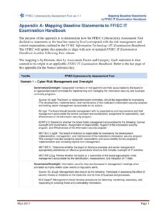
6 Another goal was to develop a sensor control scheme of autonomous sensor management. This, along with a next-generation cockpit, would provide the pilot with an unprecedented amount of information distilled down to an easily consumable format. Prior to this, the pilot spent precious minutes setting up radar scans and adjusting tilt, gain, and refresh rates, while also monitoring multiple displays to run an intercept. With this new suite, the pilot is able to view a picture of the multispectral battlespace in a consolidated format, as depicted in Fig. 1. Fig. 1 Returning the pilot to the role of tactician. The strategy for developing the avionics system was based upon a block buildup strategy. It was founded on basic warfighting capabilities and then built into the most advanced fighter weapons system currently in service. The most fundamental elements were developed first, and then the design moved to higher levels of capability.
7 In this way, the team reduced the risk of software development produced by having a single large software release. This strategy was adapted from previous tactical fighter programs, such as the F-16, and more recently, the F-22. Those programs demonstrated that it is essential to break the software development into manageable blocks to reduce the complexity and cost of testing. Incremental releases also provide more of an opportunity to manage requirements creep and incorporate technology changes that directly benefit the warfighting capability. This was evident in the F-35 program s ability to implement additional weapons ( , GBU-39) and capabilities ( , operational test support changes) to support emerging requirements. The approach is structured as three development blocks that establish the basic flight control Systems and essential Mission Systems before building up Mission capability.
8 The approach to building up the block plan in detail is depicted in Error! Reference source not Approved for public release 5/1/18, JSF18-502 3 Fig. 2 Block development buildup. ArchitectureIt was recognized early in the concept development phase that the architecture of the Mission Systems would bekey to the program s success. To succeed, many challenges had to be faced to develop the right architecture. One was that the computing resources needed for the full set of capabilities could not fit within the power, weight, volume, and thermal limitations of the air vehicle using available technology. Another was that the long development cycle and initial low-rate production was expected to result in diminishing manufacturing source (DMS) problems. In addition, the aircraft needed to be easily adaptable to support the unique needs of multiple countries. Further, it needed to be unclassified on the production line and on the ramp to avoid increased production and sustainment costs.
9 Beyond this, it also needed to operate in future battlespaces where the movement of data at multiple levels would be key to interoperability. The plan for overcoming computing resource and DMS challenges was to execute multiple technology refreshes of the computers during development. The processing update would allow Moore s law to take effect, providing increased processing capability over time that would fit within the limitations of the air vehicle. The updates would also allow updates to mitigate DMS and validate that the application software was independent of the underlying processor. To achieve the goal of making the application software independent of the processor changes, three design approaches were used. The first approach (Fig. 3) was to layer the software on top of commercial, off-the-shelf (COTS) operating Systems , under the assumption that the virtual platform would not change.
10 Fig. 3 Layered software design. Approved for public release 5/1/18, JSF18-502 4 The second approach was to use rate-based processing for all threads when timing and latency were critical. This approach would achieve constant system-level timing, even with faster processing. Also, it would enable analyzing the system and proving that it was schedulable using rate-monotonic theory. Both benefits supported easier integration, reduced regression testing, and supported airworthiness and safety certification. The third approach was to use messages for communication among all application software components, as well as components and subsystems [1]. This created controlled interfaces among the components and enabled moving applications to different processors without impacting the software. The approach contributed to solving interoperability and adapting the software for multiple countries.