Transcription of F. istr. 38512 - 5213 - All Valve
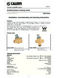
1 tempering Valve for solar and instantaneous applications 2522HP series Installation, commissioning and servicing instructions The tempering Valve is used to regulate the set temperature of mixed hot and cold water even when variations occur in the water supply conditions. The Caleffi 2522HP series has been specifically designed and manufactured to meet the requirements of AS :2005 tempering valves and end-ofline temperature actuated devices . This particular series of tempering valves has been developed primarily for installation in solar hot water systems. These valves are also suitable for use on instantaneous and general hot water storage systems. AS WMKA 02466 Product code 252212HP: 15 mm (1/2 ). 252219HP: 20 mm (3/4 ). Valves are supplied standard with union connections at the inlets and include in-line strainers and check valves. 1. Technical data Materials: - Valve body: DZR alloy EN 12165 CW602N.
2 - regulating spindle: DZR alloy EN 12165 CW602N. - internal shutter: PPO. - sealing elements: EPDM. - cap: ABS. Temperature adjustment range: 35 50 C (55 C only under supervision and not within requirements of AS 3500 and AS ). Temperature set: Must be commissioned on site to achieve desired temperature Temperature control: 3 C. Minimum cold inlet temperature: 5 C. Maximum cold inlet temperature: 30 C. Minimum hot inlet temperature: 55 C. Maximum hot inlet temperature: 100 C. Maximum working pressure (static): 1400 kPa Maximum working pressure (dynamic): 500 kPa Minimum working pressure (dynamic): 20 kPa Maximum unbalanced dynamic supply (hot/cold or cold/hot): 6:1. Minimum temperature differential between hot water inlet and mixed water outlet to ensure thermal shutoff function: 10 C. Minimum temperature differential between mixed water outlet and cold water inlet to ensure stable operation: 5 C.
3 Minimum flow rate for stable operation: 4 l/min Dimensions Code 252212HP 252219HP. C. A 15 20. B B. B 62,5 69. C 125 138. F. D 91 126,5. E 48,5 84. D. A. A. F. AS WMKA 02466. 42,5 42,5. E. D*. E*. A. * Only for 252219HP. 2. Operation A tempering Valve mixes hot and cold water in such a way as to maintain the set temperature of the mixed water at the outlet. A thermostatic element is fully immersed into the mixed water. It then contracts or expands causing movement of the piston, closing either the hot or cold inlets, thus regulating the flow of water entering the Valve . If there are variations of temperature or pressure at the inlets, the internal element automatically reacts attempting to restore the original temperature setting. Thermal shut-off In the event of a failure of the hot or cold supply, the piston will shut off, stopping water discharging from the mixed water outlet.
4 The Caleffi Valve requires a minimum temperature differential from hot inlet to mixed water outlet of 10 C to ensure the correct operation of the thermal shutoff feature. COLD. HOT. MIXED. 3. Flow rate graph p (kPa) 15 mm 20 mm 150. 140. 120. 100. 90. 80. 70. 60. 50. 45. 40. Pressure drop - kPa 35. 30. 20. 20. 18. 16. 14. 12. 10. 9. 8. 7. 6. 5. 4,5. 4. 3,5. 3. 2,5. 2. 1,8. 1,6. 1,4. 1,2. 1. 2,5. 3. 3,5. 4. 4,5. 6. 7. 8. 9. 12. 14. 16. 18. 25. 30. 35. 40. 45. 2. 5. 10. 20. 50. G (l/min). Flow rate - Litres per minute Code (mm) Kv (m3/h). 252212HP 15 1,5. 252219HP 20 1,7. Use and flow rate Caleffi series 2522HP tempering valves are typically installed at the hot water heater. In order to maintain the set temperature, the tempering Valve must have a minimum flow rate of 4 l/min. When used in instantaneous hot water systems, the most stable conditions are achieved with the hot water temperature set lower than 65 C and with a flow rate greater than 6 l/min.
5 The system should be sized in accordance with the current legislation in regard to the nominal flow rate of each outlet. The reference is AS/NZS Table 4. Exploded diagram 1 CAP. 2 LOCKING NUT. 3 TEMPERATURE ADJUSTMENT SPINDLE. 4 Valve BODY. 5 GASKET. 6 UNION NUT. 7 INSERT CHECK Valve . 8 TAIL PIECE BODY. 9 INSERT STRAINER. 1. 2. 3. 4 5 6 7 8 9. KIT A. 5. Installation The Caleffi 2522HP series must be installed by a licensed plumber. The installer has a duty of care to ensure that all aspects of the installation comply with the AS/NZS 3500, appropriate Codes of Practice and/or local government requirements. Prior to the installation of the Caleffi 2522HP series Valve , the system must be checked to ensure that the system operating conditions fall within the recommended operating range of the Valve , verify supply temperatures, supply pressures, risk assessments, etc. Also, be aware of all current legislation, the maximum distance from the outlet of the Valve to any terminal fitting, etc.
6 The supply system must be thoroughly flushed and cleaned to remove any debris which may accumulate during the installation. Failure to remove any debris will affect the performance and may void the manufacturer's warranty. In areas that are subject to high levels of aggressive water, provision must be made to treat the water prior to it entering the Valve . The Valve can be installed in any position, vertical or horizontal. To allow for maintenance, it is important that access to the Valve and fittings is not impeded. The hot and cold water supplies must be connected to the Valve strictly in accordance with the indications on the body of the Valve . The inlets of the valves are clearly marked with the letter H (Hot) and C (Cold). The outlet is marked with the word MIX. Where one or both of the incoming supply pressures are excessive, a Caleffi pressure reducing Valve should be fitted to reduce the pressure(s) to within the limits as quoted previously.
7 Any tempering Valve should be installed with isolating valves, line strainers and check valves at both the inlets. The Caleffi 2522HP series is supplied complete with line strainers and check valves at the hot and cold inlets. Strainers prevent debris from entering the Valve and the check valves at both hot and cold inlets prevent cross-connection. Installing isolating valves should be considered so the Valve can be isolated during commissioning or if servicing is required. The pipework must not be used to support the weight of the Valve . If the Valve is not installed correctly then it will not function correctly and may put the user in danger. Installation diagram MIXED T < 50 C. OUTLET. HOT SUPPLY COLD SUPPLY. T. WMKA 02466. AS Temperature Pressure Isolating Strainer Strainer Isolating Pressure limiting Valve reducing Valve Valve & check & check Valve reducing Valve Valve Valve (if required) (if required) (if required).
8 6. Application diagrams Solar system SOLAR. HOT WATER. STORAGE. MAINS. SUPPLY. System without recirculation HOT WATER. STORAGE. HEATER. MAINS. SUPPLY. System with recirculation HOT WATER. STORAGE. HEATER. MAINS. SUPPLY. 7. Instantaneous INSTANTA- system NEOUS. WATER. HEATER. MAINS. SUPPLY. Commissioning After installation, the Valve should be tested and commissioned in accordance with AS , as per the procedure outlined below or as specified by the local authority. The following instructions should be read and understood prior to commissioning the Caleffi 2522HP series Valve . If, under any circumstances, there are aspects of the installation/system which do not comply with the requirements or the specifications as laid down, the Valve must not be put into service until it does comply. 1) Ensure that the system is thoroughly clean and free from debris prior to commissioning the tempering Valve .
9 2) Measure the mixed water temperature at the nearest outlet (we recommend using an accurate digital thermometer). 3) The temperature of the mixed water supplied to an outlet primarily for personal hygiene purposes shall be in accordance with the requirements of AS/NZS 3500. 4) Once the supply temperatures and normal operating conditions have stabilised, the Valve can be commissioned. The temperature setting can be adjusted by removing the cap and rotating temperature adjustment spindle. We suggest that the following sequence is followed when commissioning the Valve . a) Set the mixed water discharge temperature to the required temperature. b) Measure the temperature of hot and cold water at the inlets of the Valve . c) Measure the temperature of discharged mixed water for high and low flow conditions. d) Perform the thermal shut-off test, by isolating the cold water supply to the Caleffi 2522HP.
10 Valve and monitor the mixed water temperature. The outlet flow should quickly cease. e) Restore the cold water supply to the Valve and measure the mixed water temperature when it has stabilised. The final temperature found during this test should not exceed the set temperature by +3 C. 5) Once commissioning is completed, lock the temperature adjustment spindle using the locking nut supplied and secure the cap back on to the Valve to prevent tampering by unauthorised persons. 6) Complete the tempering Valve FITTED label and affix it to the water heater (or where required by the Local Authority). 8. Temperature adjustment 1 Remove the cap 2 Direction of temperature adjustment 3 Temperature adjustment 4 Lock adjustment spindle with locking nut 9. Maintenance Tests should be carried out periodically to monitor the performance of the Valve in accordance with AS Deterioration in performance can indicate the need for varying water supply conditions and/or maintenance or replacement of the Valve .


