Transcription of Fabrication and erection of Tokyo Gate bridge - iabse-bd.org
1 IABSE-JSCE Joint Conference on Advances in bridge Engineering-III, August 21-22, 2015, Dhaka, Bangladesh. ISBN: 978-984-33-9313-5. Amin, Okui, Bhuiyan, Ueda (eds.) Fabrication and erection of Tokyo gate bridge T. Yoneyama Kawada Industries, Inc., Toyama Plant, Nanto-city, Toyama, Japan Y. Fujii Kawada Industries, Inc., Tokyo Head Office, Tokyo , Japan ABSTRACT: Tokyo gate bridge was planned to mitigate traffic congestion on coastal roads around Tokyo Port and to provide access to a future logistics hub. In engineering, there were two major restrictions; airspace above the bridge due to proximity to Haneda Airport and seaway clearance beneath the bridge for vessel pas- sage. These constrains resulted in selection of a composite structure with steel truss members and a steel box girder in lieu of a cable-stayed or a suspension structure. In order to save construction cost, several signif- icant measures were adopted.
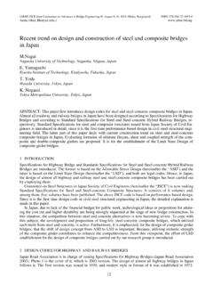
2 They include use of newly developed SBHS (Steels for bridge High Perfor- mance Structure) and large block erection using three heavy duty floating cranes. 1 FACTS AND CHALLENGES. The bridge is located just outside of the Tokyo Port, which is one of the busiest ports in the world and which has future expansion plan including new container terminals. The bridge is expected to improve traffic and to mitigate approaching routes congestion. It is located near Haneda International Airport. Under the bridge there is Tokyo Port's Seaway #3 for the vessel traffic. Therefore the bridge has the following challenges. -Overall structure's height shall not exceed meter in order to assure clearance for incoming and outgoing air traffic to and from the airport. -For 300 meter seaway, under bridge clearance shall be at least meter for 60000 ton class vessels and the world's largest cruise ships such as the Queen Elizabeth II.
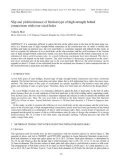
3 Figure 1. Geometrical Restriction of the bridge In order to achieve the above challenging requirement, the bridge type was elected to be of a composite struc- ture with steel truss members and a steel box girder in lieu of a cable-stayed or a suspension structure. General information of the bridge is shown in the following figure. 268. Figure 2. General Information of Tokyo gate bridge 2 THE bridge 'S KEY FUTURES FOR ENGINEERING AND CONSTRUCTION. The following are the key futures of design, Fabrication and erection of the bridge . i. Use of Newly developed High Performance Steel for bridge -SBHS Steel ii. All Welded Joints for Main Truss Members iii. Orthotropic bridge Deck iv. Eliminating shop trial assembly, the side span truss bridge sections were fabricated at shop and as- sembled in the yard close to the erection point as erection blocks. v. erection of the two large blocks with well synchronized performance of 3 heavy duty floating cranes vi.
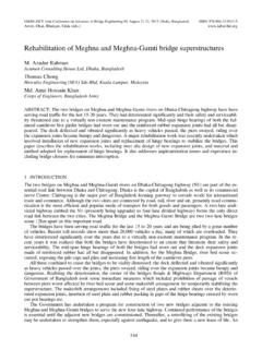
4 Among those above, this paper will be focused on Fabrication using newly developed SBHS steel . and erection of the large blocks with 3 heavy duty floating cranes . 3 Fabrication USING SBHS STEEL. Outline of SBHS Steel The project used significant amount of newly developed SBHS Steel : Steels for bridge High Performance Structure, with high tensile strength as 570 N/mm2 or above (to be called SBHS steel in this paper). The location of SBHS steel application and the amount used are shown in the following figure. We were able to save 600 tons (3%) of steel usage comparing to regular JIS SM570 steel (Ts=570 N/mm2 or above : to be called 570 N steel in this paper). Figure 3. Members where SBHS steel was used 269. Table 1. SBHS500 Steel _____. Total Steel Weight : Approximately 20,500 tons SBHS Steel Included : Approximately 10,300 tons (51%). _____. SBHS steel features high-performance, high-tensile strength that was developed through a joint project car- ried out by industry and academia for the purpose of reducing steel bridges' construction costs in Japan.
5 The specifications for the material grade of SBHS-SBHS500 that was used for the bridge are shown in the following table. Table 2. Specifications of SBHS500 steel Chemical composition C Si Mn P S N. (%) (%) (%) (%) (%) (%). Mechanical YP TS Elongation Toughness properties Thickness range Elongation Temperature Energy Direction (N/mm2) (N/mm2) (mm) (%) ( C) (Joule). 500min, 570~720 6 up to 16 19min. -5 100min. Transversal to roll direction Over16 up to 20 26min. -5 100min. Transversal to roll direction Over 20 20min. -5 100min. Transversal to roll direction It has the following advantages;. i. Higher yield strength than conventional steel (constant yield strength irrespective of sheet thickness). ii. Greater ease of Fabrication and welding than conventional 570 N steel, eliminating preheating in some cases, and enabling reducing preheating temperature. iii. Charpy test conducted perpendicular to rolling direction; Toughness is high at any plate rolling di- rection.
6 Iv. Improves ease of welding and cold Fabrication , etc.; improves formability in manufacturing SBHS steel is produced by high-tech thermal process controlling and by adding synthetic element so that it has higher precipitation strength and finer crystalline structure. As a result, SBHS steel is low carbon alloy and yet it has high strength and high toughness. It also has as good workability as JIS SM 490Y class steel (Ts=490 N/mm2 or above : to be called 490 N steel in this paper). Tests to Confirm Workability for SBHS Steel Prior to Fabrication work, a series of tests were conducted in order to confirm those advantages of SBHS steel for thermal cutting, cold bending, heat straightening, preheating and weldability. Thermal cutting Thermal cutting was performed using the same work parameters as 490N steel and no problem such as rough cut surface , sticky slag or edge melting was observed.
7 Cold-bending After bending with radius=5 times of thickness, the Charpy V-notch value (vE-5) still exceeded 200J for both longitudinal and transverse directions, while SBHS specifications requires that after bending with radius=7xt, the Charpy V-notch value (vE-5) shall be 100 J min. Table 3. Charpy Test Result Treatment Strain Aging Impact Test Specimen thickness/4. Sampling Location Direction vE-5 average vTrs Joule C. Longitudinal 273 -45. Transversal 298 -40. 270. Heat straightening After liner heating 1000 C and either air-cooling or water-cooling, the tensile strength and Charpy V-notch toughness value still exceeded requirement. Table 4. Heat Straightening Methods for Comparison Method# Heat Temperature Cooling Gas Height of Torch Water Applied 1 900 C Air O2* and C2H2** 14mm None 2 900 C Water O2* and C2H2** 14mm 6 liter per minute 3 1000 C Air O2* and C2H2** 14mm None 4 1000 C Water O2* and C2H2** 14mm 6 liter per minute *Pressure 5kg/cm2 Flow Rate 50 liter per minute **Pressure Flow Rate 20 liter per minute Table 5.
8 Heat Straightening Method Comparison Result Method# Transversal Direction 1mm under Surface Mechanical Test Impact Test Result Yield Point Tensile Strength Elongation Direction vE-5. (N/mm2) (N/mm2) (%) (Joule Average). 1 534 637 30 Longitudinal 1 ditto ditto ditto Transverse 2 536 637 28 Longitudinal 2 ditto ditto ditto Transverse 3 529 633 29 Longitudinal 3 ditto ditto ditto Transverse 4 538 637 29 Longitudinal 4 ditto ditto ditto Transverse Preheating Y-groove weld cracking tests were performed on GMAW welding and SMAW welding with no preheating (room temperature 6 C) and no crack was detected. Table 6. Welding Procedure Test with No Preheating Welding Process SMAW. Welding Consumable L-62CF. Diameter 4mm Preheating None (Room Temperature 20 C). Humidity 60%. Parameter 170 Amp-25 Volt-15cm/minute Heat Input Drying Consumable 400 C for 1 hour Stored at 110 C No Moisture Absorption Result NO CRACK DETECTED.
9 Welding Process GMAW. Welding Consumable YM-60C. Diameter Preheating None (Room Temperature 20 C). Humidity 60%. Parameter 280 Amp-30 Volt-30cm/minute Heat Input Drying Consumable CO2 25liter/minute Result NO CRACK DETECTED. Weldability Welding procedure tests with two processes were conducted. One was by CO2-GMAW with heat input under 5KJ and interpass temp under 250 oC. Another one was SAW double electrodes in tandem with heat input un- der 10 kJ and interpass temperature under 300 oC. Both welding processes were proven to be satisfactory with the tensile strength and Charpy toughness exceeding requirement. 271. Summary of the procedure test results While conventional 570N steel tends to have more restricting factors that 490 N steel for cutting because of more alloy ingredients, SBHS steel is as easy to cut as regular 490 N steel. SBHS steel can be bent to 5 x thickness radius and it is equal to regular 490 N steel.
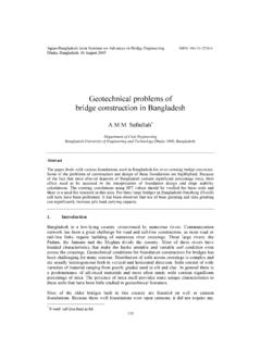
10 Heat straightening up to 1000 C and water cooling still resulted in all sound steel mechanical properties. All the welding procedure tests with minimum heat input and no preheating caused no cracking on Y-groove weld cracking tests. These results proved that we do not need preheating. Both SAW welding with heat input 100 KJ/cm and CO2-GMAW welding inter-pass temper- ature over 230 C(specified for JIS 570 N steel) produced sound and acceptable mechanical properties. Supported by the above procedure test results, the Fabrication was performed with NO preheating. Figure 4. Fabrication Photo The fabricated members were then transported to the assembly yard near erection point to complete erection block assembly. Figure 5. Yard Assembly and Completing erection Block at Ariake Yard 4 erection . General Side span unit weighs approximately 6800 tons and including lifting assembly the overall erection block ended up with 7400 tons.