Transcription of Facilities Development Manual
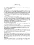
1 Page 1 Facilities Development Manual Wisconsin Department of Transportation Chapter 15 Plan Preparation Section 5 Methods FDM 15-5-1 General January 13, 2017 This section contains the basic information required for preparing and submitting contract plans.
2 If additional information is desired, contact the design supervisor or the Proposal Management Section in the Bureau of Project Development . The requirements for such plans using Computer Aided Design and Drafting Systems (CADDS) are contained in FDM 15-5-2. Notice: Electronic plans are the only acceptable method of plan preparation. Surveying and Mapping Section All photogrammetric mapping and DTM data for plan preparation are provided by the Surveying & Mapping Section in the Bureau of Technical Services. Exact plan coverage is determined by the region and subsequently ordered from Surveying & Mapping. Refer to FDM 9-45-1 for information on how to order photogrammetric mapping and DTM data. Plan Development The following standards are based on the preparation of 11 x 17 plans. Format: All contract plan sheets shall conform to the standards listed in FDM 15-5-5 for size and composition.
3 Lines and Art Work: Black ink shall be used and must appear continuously. Minimum pen width should be a zero weight ("0" - in) rapidograph. Double zero weights ("00" - in) are only acceptable for items such as crosshatching. Line weights shall be uniform with sufficient opacity to ensure acceptable reproduction. Lettering: Lettering shall be placed by computers, or typewriter. It should be in a style and clarity consistent with accepted engineering drafting practice. Minimum acceptable height is " (60 LEROY, or equivalent), except that " (50 LEROY or equivalent) is permissible on R/W plats. Stamping of plan notations is generally unacceptable due to poor reproductive quality. Professional seals affixed to the title sheet must be applied with even pressure, utilizing a fast drying, opaque ink. Simplicity: Drawings should be kept simple. Eliminate repetitive details and unnecessary views, lines, and dimensioning.
4 Electronic Plans (E-Plans) E-Plans are the only plan submittal format. E-Plans must be complete including signed & sealed title sheet, and sealed sheets where applicable. Not included are sign plates, SDD s, and structures. Follow the standards set in FDM 15-5-10 and FDM 19-10-1 for the preparation and submittal of electronic plans. FDM 15-5-2 CADDS Preparation Standards January 13, 2017 This procedure describes the requirements for preparing and recording maps and plans for highways using Computer Aided Design and Drafting Systems (CADDS). Electronic copies of design files are available for download from the internet at the following location: Note: Photogrammetric mapping conforms to the Surveying and Mapping Photogrammetric Specifications for MicroStation version J/7. Photogrammetric mapping/DTM conforms to the FDM for MicroStation version 8. The use of AutoCAD Civil 3D software and file formats native to it will be required on most highway projects.
5 Further information is included in FDM 19-10-43 and FDM 19-10 Attachment Where applicable, preparation standards are specified separately for files developed in MicroStation/CAiCE and AutoCAD Civil 3D. There are two reasons for this differentiation: - The software packages have different file structures and options within those structures. - The Department is requiring the full design project be submitted for projects developed in AutoCAD Civil requirement ensures that the Department does not lose any file connections, object intelligence, design analysis, or design intent that was part of the project. FDM 15-5 Methods Page 2 Design Files File Format The graphical data submitted shall be in accordance with digital data exchange standards.
6 Refer to FDM 19-10-43. File Ownership When CADDS are used by consultants or outside agencies to develop project plans and the Development contract is completed or terminated, a digital copy of the files shall be delivered to and become the property of the Department of Transportation. Refer to FDM 19-10-43 for delivery methods and requirements. Graphical Parameters Graphic parameters such as level, color, weight and line code (style) shall follow the standards as specified in the following locations: - Microstation DGN - The parameters are found in the level library located on the WisDOT internet site at: Under , click on . - Civil 3D DWG - The parameters are found in the master template file on the WisDOT internet site at: Weights Line weights shall be similar to those required for manually prepared documents. For printing or plotting a 11 x 17 sheet, the line weight base of inches is used for a 4 weight.
7 Weight Inches (MicroStation/CAiCE Inches (Civil 3D) 0 1 2 3 4 5 6 7 8 If reduced size plans are to be submitted then the weight base and increment should be reduced proportionately. Line Styles Only DOT custom line styles will be accepted. All non-DOT custom line styles must be converted to individual elements. Note that each line style is named with a preceding E in the resource libraries to indicate English. If custom line styles cannot be used, the corresponding linear pattern cell is indicated in the Symbol column. Symbol If the symbol cell cannot be used, all symbols must conform with the standard symbols covered elsewhere in this Manual . The use of shared cells will not be accepted. All shared cells must be converted to non-shared cells or individual elements. Note that the cell libraries are named with a preceding E indicate English.)
8 Lettering Minimum size lettering shall be equal to a 60 Leroy ( ) size on an 11"x17' sheet. A 50 Leroy ( ) is permissible on R/W plats only. FDM 15-5 Methods Page 3 English Text Sizes (inches) Leroy Guide Weight 200 =1 100 =1 40 =1 250 8 175 5 100 3 2 70 1 60 0 Calibri Light/Font 5 shall be used for general drafting work and Arial Light/Font 15 or Calibri Light/Font 20 are acceptable for work requiring uniformly spaced characters.
9 These fonts are designed to approximate the appearance of Leroy lettering. Graphical parameters such as level, color, weight and line code (style) specified in this chapter also apply to text elements. Screening Screening refers to the effect applied to existing data and sheet grids at the time of print or plot. Screening is represented by gray shading. Gray shading is a 30% toner reduction causing the lines to print gray. In MicroStation version , levels 1-211, 231, 60 and 61 are typically screened. In other file formats, levels, or layers named with a prefix E_ are typically screened. Exception: All information on a Transportation Project Plat shall be shown as black on white with no gray shading. FDM 15-5-3 CADDS Directory and File Name Convention March 16, 2018 CADDS files for highway project design documents are required to be maintained for up to twenty years.
10 Project documents stored in active or archived CADDS files should be readily retrievable without recourse to file names which require extra documentation or indexes for the CADDS highway project documents. The following directory and file naming conventions will satisfy the retrieval concerns while meeting the requirements of the department host-based filing system. The requirements for the directory names shall apply to department staff developed CADDS projects. Outside organizations, such as consultants, who utilize CADDS to develop projects, are required to satisfy only the specifications for file names within the design project. Project Directory Conventions AutoCAD Civil 3D Civil 3D projects contain all the geographic and CADDS files for a project. The standard WisDOT project structure included in the resource files at: The project directory shall be the design project number, eight characters long.