Transcription of FAIRCHILD T7800 STANDARD RANGE MINIATURE …
1 1 Figure 1. Model T7800 STANDARD RANGE transducer Identification Number SystemFAIRCHILD T7800 STANDARD RANGE MINIATURE ELECTRO-PNEUMATIC TRANSDUCERI nstallation, Operation and Maintenance Instructions Model T7800 Series of Electro-Pneumatic transducer converts a DC input signal to a linearly proportional pneumatic output INFORMATIONSPECIFICATIONSM inimumSpan3-15[ ](20-100)4-20 mA DC, 0-10 VDC, 1-9 VDC, 0-5 VDC, 1-5 VDC 20-120[ ](150-800)5[ ](35)3-27[ ](20-180)10[ ](70)32-120[ ](220-800)6-30[ ](40-200)35-120[ ](240-800)10[ ](70)psig[BAR](kPa)psig[BAR](kPa)psig[BA R](kPa)Functional SpecificationsOutputRangeSupplyPressureI nputRangeOperating .. Storage .. Required OperatingVo l t a g e sSupplyVoltageS i g n a lImpedanceTwo Wire Current InputThree Wire Voltage InputThree Wire Voltage InputTemperatureRangeS p a n / Z e r oAdjustmentsScrewdriver adjustments located on front of VDC @ 20 mA (4-20 mA signal)7-30 VDC, less than 3 mA10 KilohmsFlow Rate( S C F M )A i r C o n -s u m p t i o nAll Ranges(SCFH)Set Point3 psig[ BAR](20 kPa)9 psig[ BAR](60 kPa)15 psig[ BAR](100 kPa)30 psig[ BAR](200 kPa) ( /HR) @25 psig, [ BAR], (170 kPa) supply & 9 psig, [ BAR], (60 kPa) ( /HR) @ 120 psig, [ BAR], (800 kPa) supply & 9 psig, [ BAR], (60 kPa) (.)
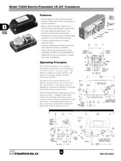
2 10 m /HR) (.27 m /HR) (.38 m /HR) (.20 m /HR)or3333-40 F to +180 F (-40 C to + C) -40 F to +160 F (-40 C to + C) 2 INSTALLATIONPart of the TDFI7800 enclosure is constructed of Non-Metallic material. To prevent the risk of electrostatic sparking, the en-closure shall only be cleaned with a damp cloth. The TR7800 transducer is designed for use with the TR Rack Kit. Physically, it is the same as the TT7800 (Terminal Block) unit except that the terminal block has been rotated to the back. For more informa-tion, see Figure 6. NOTE: Figure 3. Mounting Kit 16799-1 (included with unit)Figure 2. TA7800 Outline DimensionsYou can mount the Model T7800 on a flat surface using two 10-32 Screws. For more information, see Figure 2. The Model T7800 ships from the factory with Mounting Kit 16799-1 for Panel or Wall Mounting and Mounting Bracket Kit 16893 for Din Rail Mounting.
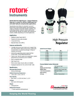
3 For more information, see Figure 3 and Figure optional mounting kit, 19254-1, is available to install the unit on a 2" pipe. For more information, see Figure 8. Figure 4. TT7800 Outline DimensionsFigure 5. TD7800 Outline DimensionsFigure 6. TR7800 Outline DimensionsFigure 7. Din Rail Mounting Kit 16893 (included with unit)3 Figure 8. Optional Mounting Kit 19254-1 (sold separately)Figure 9. Connexions lectriquesElectrical ConnectionsMake connections to the Terminal Block, Conduit Connector or the DIN Connector as shown in Figure 9. Pneumatic ConnectionsClean all pipelines to remove dirt and scale before installation. Apply a minimum amount of pipe compound to the male threads of the air line only. Do not use teflon tape as a sealant. Start with the third thread back and work away from the end of the fitting to avoid contaminating the transducer .
4 The inlet and outlet ports are labeled on the ends of the transducer . Tighten all connections securely. Avoid undersized fittings that will limit the flow through the transducer . For more information, see Figure 2. NOTE:Instrument quality air, per ISA Standards , is required. Use a filter to remove dirt and liquid in the air line ahead of the transducer . If an air line lubricator is used, it MUST be located downstream to avoid interference with transducer user is responsible for ensuring that the environment in which the unit is installed and the operating gas are compatible with the materials in the transducer . 4 FULL- RANGE OPERATIONLo/Hi Span Adjustment Acting Mode Adjustment 2. Forward Acting Calibration - Zero 3. Forward Acting Calibration - Span 4.
5 Acting Mode Adjustment NOTE: 6. Reverse Acting Calibration - Zero 7. Reverse Acting Calibration - Span 8. OPERATIONLo/Hi Span Adjustment1. Set the Lo/Hi Span switch to the Lo position for 3-9 psig or 9-15 psig output RANGE and for 4-20 mA input RANGE . Set the Lo/Hi Span Switch to the Hi position for 3-15 psig output RANGE for 4-12 mA or 12-20 mA input RANGE . For more information, see Table / ADJUSTMENTSE quipment Required for Calibration Pneumatic supply capable of delivering up to 120 psig Current supply capable of delivering up to 30 mA Pressure gauge capable of a digital readout up to 50 psig with an accuracy of Digital volt meter capable of a readout up to 30 mA with an accuracy of .02%The following adjustments are provided: Full RANGE Operation Lo/Hi Span Forward/Reverse Mode Calibration - Zero and Span Split RANGE Operation Damping AdjustmentsSet the Lo/Hi Span Jumper to the Lo position for 3-15 psig output RANGE .
6 Set the Lo/Hi Span Jumper to the Hi position for 3-27 or 6-30 psig output RANGE . For more information, see Table Fwd/Rev Mode Jumper to Forward the minimum input signal and adjust the Zero Adjustment for minimum output the maximum input signal and adjust the Span Adjustment for maximum output steps 3 and 4 until the desired output RANGE is Fwd/Rev Mode Jumper to the Reverse the maximum input signal and adjust the Zero Adjustment for minimum output pressure. Apply the minimum input signal and adjust the Span Adjustment for maximum output steps 7and 8 until the desired output RANGE is Damping Adjustment lets you tune the transducer for optimum response and stability in a particular best performance, start the Damping Adjustment at maximum adjustment, fully clockwise.
7 Gradually turn counterclockwise until slight oscillation occurs. Turn back clockwise until oscillation is minimized. For more information, see Figure 10. Turn Damping Adjustment clockwise to increase damping Damping Adjustment counterclockwise to decrease damping NOT reverse the input leads. 1. Adjustments Damping AdjustmentForward Acting Mode Adjustment2. Set Fwd/Rev Mode Jumper to the Forward Acting Calibration - Zero3. Apply the minimum input signal and adjust the Zero Adjustment for minimum output Acting Calibration - Span4. Apply the maximum input signal and adjust the Span Adjustment for maximum output Repeat steps 3 and 4 until the desired output RANGE is Acting Mode AdjustmentNOTE: Do NOT reverse the input leads6. Set Fwd/Rev Mode Jumper to the Reverse Acting Calibration - Zero7.
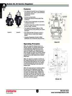
8 Apply the maximum input signal and adjust the Zero Adjustment for minimum output Acting Calibration - Span8. Apply the minimum input signal and adjust the Span Adjustment for maximum output Repeat steps 7 and 8 until the desired output RANGE is 10. T7800 Calibration ConfigurationCalibrations / Adjustments (continued)6 Figure 11. Exploded Drawing1221111111111311112 Table 5. T7800 transducer ComponentsDescription 1 2 3 4 1 5 6 1 7 8 1 9 11011 112 11314151617 , MachiningScrewScrewGasketNozzle Body AssemblyOrifice AssemblySpringDiskDiaphragmSpacer RingDiaphragm AssemblyFoam BlockValve Body AssemblyScrewPintleSpring, PIntleO-RingPlugScrew1 19267-1 Service Kit Components. 3-15, 3-27, 6-30 psig [ , , BAR] (20-100, 20-180, 40-200 kPa) off the valve that supplies air to transducer .
9 It is not necessary to remove the transducer from the air the Orifice Assembly (6) from the unit. For more information, see Figure with alcohol and dry with compressed clean the Orifice, use the following procedure:MAINTENANCEP arts must be completely dry before the STANDARD maintenance procedure does not correct the problem, install the appropriate service kit. NOTES:TROUBLESHOOTINGT able 6. TroubleshootingProblemSolution (check) Supply pressure Clogged orifice Connections Zero and Span adjust Low supply pressure Output leakage DC signal Loose wires or connections Liquid in air supplyNo outputLeakageLow or improper Span adjustErratic operationWARNING: transducer failure could result in output pressure increasing to supply pressure and possibly causing personal injury or damage to AREA CLASSIFICATIONFM (Factory Mutual) Approvals: Intrinsically Safe: Catalog Versions: TAFI7800, TDFI7800 Class I,II,III Div 1 Groups CDEFG T4 ED-18970; Entity I/O AEx ia IIB T4 -40 C to +80 CNon-Incendive: Class I, Division 1, Groups C and D; Temperature Code T6.
10 Class I, Division2, Groups A, B, C and D; Class II, Division 2, Groups E, F, and G; Type 4 Enclosure; Rated 4-20 mA, 30 VDC Maximum; Temperature Code T6. CSA (Canadian Standards Association) Approvals: Intrinsically Safe: (4-20 mA only) (TDCI7800, TACI7800) Division 2 Approvals: (4-20 mA only) (TDCI7800, TTCI7800, TRCI7800) Class I, Division 2, Groups A, B, C and D; Rated 4-20 mA, 30 VDC Maximum; Temperature Code T6. (TACI7800) Class I, Division 1, Groups C and D; Class II, Division 1, Groups E, F, and G; Type 4 Enclosure; Rated 4-20 mA, 30 VDC Maximum; Temperature Code T6. (TTCI7800, TRCI7800)Approvals are valid when connected through a Shunt Zener Diode Safety Barrier meeting the following parametric requirements:System Type 2: Dual Channel Polarized Rated: Max.