Transcription of FAN DRIVE INSTALLATION, OPERATION AND …
1 FAN DRIVEINSTALLATION, OPERATION AND MAINTENANCE INSTRUCTIONS22656-C-06072 INTRODUCTIONG eneral InformationThis manual describes the correct Fan DRIVE installation procedures. Following the instructions carefully will provide the safest and most trouble-free uses the following special notices to give warning of possible safety related problems which could cause serious injury and provide information to help prevent damage to is used to indicate the presence of a hazard which will cause severe personal injury, death, or substantial property damage if the warning is is used to indicate the presence of a hazard which can cause severe personal injury, death, or substantial property damage if the warning is is used to indicate the presence of a hazard which will or can cause minor personal injury or property damage if the warning is is used to notify people of installation , OPERATION .
2 Or maintenance information which is important but not hazard N T R O D U C T I O N 2 G e n e r a l I n f o r m a t i o n 2P R E V E N T I V E M A I N T E N A N C E 2P R E - I N S TA L L AT I O N 3I N S TA L L AT I O N 4 Ve h i c l e P r e p a r a t i o n 4 F a n D r i v e I n s t a l l a t i o n 4E L E C T R I C A L C O N N E C T I O N S 5 E l e c t r i c a l l y N o r m a l l y C l o s e d ( N.)
3 C . ) 5 E l e c t r i c a l l y N o r m a l l y O p e n ( N . O . ) 7 E l e c t r o n i c a l l y C o n t r o l l e d E n g i n e s 81. Before performing work on the Fan DRIVE , be sure to follow good shop safety practices. Turn the vehicle ignition off, apply the vehicle's parking brake, and block the vehicle's sure engine is turned off and fan has stopped turning before approaching fan area, to prevent serious personal PreparationPREVENTIVE MAINTENANCEWARRANTyFor product specific warranty information, please visit the Horton online Literature Order Center at or call Horton Customer Service at 25,000 MilesFan and Fan BeltFan and Fan Belt problems can cause product failure if left Check the fan for looseness and damage, such as bent, cracked or missing blades, loose rivets or missing weights.
4 Retorque if loose. Replace if Check for adequate clearance between the fan and the fan shroud or other engine compartment components in both the engaged mode the and disengaged mode. Repair if the clearance is Check the fan belt condition, belt tension, and belt alignment. Correct if necessary. Service Part DateVehicle Mileage2. Before doing work in the area of the fan: Start the vehicle s engine and build air pressure in excess of 90 PSI. Manually engage and disengage the Fan DRIVE . Observe the fan and Fan DRIVE from a distance, look for vibration, fan blade contact, Fan DRIVE slippage, and Fan DRIVE OPERATION . Turn Engine WeekDrain Air Filter (if equipped).If moisture or contamination is detected, the filter must be disassembled and flushed thoroughly with clean parts solvent.
5 Dry carefully before reassembly. Determine the cause of the moisture or contamination and correct the must follow your company safety practices, which should adhere to or be better than Federal or State approved shop safety practices and procedures. Be sure that you understand all the procedures and instructions before you begin work on this replacement and/or repair of your Horton DriveMaster Fan DRIVE should be performed only by the Horton Factory or an authorized Horton Distributor or Dealer to keep your warranty coverage intact during the warranty installation of your Horton DriveMaster Fan DRIVE , note the Fan DRIVE Service Part No., Date of installation , and Vehicle INSTALLATION1. Turn the vehicle ignition off, apply the vehicle's parking brake, and block the vehicle's the radiator from possible damage from the fan during fan removal and fan DRIVE If applicable, remove the existing fan, fan DRIVE , mounting hardware and DRIVE Installation1.
6 Position the Horton Fan DRIVE on the engine and align the holes for engines have multiple mounting locations. Be sure to use the correct holes for the Tighten the SAE Grade 8 mounting bolts and/or nuts to the vehicle manufacturer's belt adjustment and alignment is necessary for all belt driven components to assure longevity of component life. Over tightening of belts will shorten bearing life. Loose belts will cause excessive belt wear and shorten bearing life. Consult the equipment manufacturer and/or engine manufacturer specifications for proper belt Replace and adjust the Horton Fan Drives incorporate a belt tension feature into the Fan DRIVE mounting bracket. Use this feature if applicable. Steps 1-3 Fan DriveFanGrade 8 Mounting BoltsGrade 8 NutsThe maximum fan diameter is 32''.
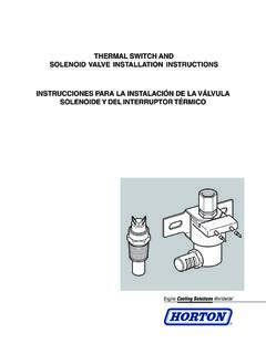
7 If a larger fan diameter is required, contact Horton at Preparation22656-C-060754. M o u n t t h e f a n o n t o t h e F a n D r i v e a n d t i g h t e n the bolts and/or nuts to the vehicle manufacturer's Drain the appropriate amount of engine coolant from the system before thermal switch Remove the pipe plug from the engine coolant manifold and install the Thermal Switch. (Location of the pipe plug may vary.) NOTEL ocate the Thermal Switch as close to the engine coolant thermostat as possible. The Thermal Switch setting should engage the Fan DRIVE at least 10o F higher than the engine thermostat Mount the Solenoid Valve in an upright position on either the vehicle's fire wall or radiator support, in an area where the Solenoid Valve will not be subjected to engine heat, vibration, or road Connect an air hose from the vehicle's air supply to the Solenoid Valve inlet vehicle's air supply must be clean and free of moisture and Check for proper air pressure to the Fan DRIVE .
8 This measurement should always be taken at the Fan DRIVE air inlet AIRSOURCECLEANAIR TOFAN TOFAN DRIVEDRY AIRSOURCE Step 6 Steps 6-7 Thermal SwitchNOTETo assure maximum performance of the Fan DRIVE and to prevent damage to the Fan DRIVE , there must be a minimum pressure of 90 PSI to the Fan DRIVE upon Affix the Warning sticker to a highly visible area of the engine compartment. Step 10 ELECTRICAL CONNECTIONS Electrically Normally Closed ( )NOTEThe Horton DriveMaster Fan DRIVE is spring engaged, air disengaged. An electrical system wired will require a normally closed Solenoid note the Thermal Switch, Freon Pressure Switch, and Solenoid Valve are the only controls absolutely necessary for fan DRIVE OPERATION . The manual Switch, Air Pressure Switch, and Indicator Light are all optional controls and may be left out of the Remove the battery cables from the Install the Air Pressure Switch into the air line between the Solenoid Valve and the Fan Steps 1-13 NOTEThe Manual Toggle Switch is stamped OFF and ON.
9 OFF position is for continuous OPERATION , ON position is for automatic OPERATION . Set the Manual Toggle Switch to ON position and note this position for future Install the Freon Pressure Switch into the high pressure Freon line of the air conditioning Connect the Black lead of the Solenoid Valve to the vehicle Connect the Red (12 Volt) or Green (24 Volt) lead of the Solenoid Valve to one lead of the Freon Pressure Switch7. Connect the other lead of the Freon Pressure Switch to one terminal of the Thermal Connect the other terminal of the Thermal Switch to one terminal of the Manual Toggle Connect the other terminal of the Manual Toggle Switch to the vehicle accessory or ignition Connect one terminal of the Air Pressure Switch to the vehicle Connect the other terminal of the Air Pressure Switch to the Indicator using the Air Pressure Switch, it must be installed in the air line between the Solenoid Valve and the Fan DRIVE .
10 Minimize the length of air line between each of these components. 12. Connect the other terminal of the Indicator Light to the vehicle accessory or ignition Connect the battery cable to the System OPERATION CheckKeep hands and tools clear of the fan blades. The Fan DRIVE can engage without With the engine temperature below the Thermal Switch setting, turn on the ignition and build up air Disconnect one terminal of the Thermal Switch. This will engage the Fan DRIVE (air should 3. Mount the optional Indicator Light and Toggle Switch on the dashboard or other convenient from the Solenoid Valve).3. Reconnect the terminal of the Thermal Switch. This will disengage the Fan Repeat Steps 1-3 for the Freon Pressure Set the Manual Toggle Switch to OFF.