Transcription of FAS 15 mm MICROSOL Direct acting solenoid valve
1 FAS 15 mm microsol direct acting solenoid valve 01/16en policy is one of continued research and development. We therefore reserve the right to amend, without notice, the specifications given in this document. (2007 - 5019e) 2015 Fluid Automation Systems :Air, oxygen, neutral gases(10 % to 95 % humidity, noncondensing), 40 m filteredOperation: Direct acting 2-way and 3-way valves , normally closed and normally openedOperating pressure:see table below page 2 Flow:6 .. 120 l/min at 2 bar (29 psi)at +20 C (+68 F)kv factor:0,15.
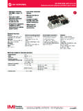
2 3 (Cv: .. )Mounting:ManifoldOrifice:2/2 way valves0,5 .. 3,6 mm ( .. )3/2 way valves0,5 .. 1,5 mm ( .. )Response time:10 .. 15 msResponse time measuredaccording to ISO 12238 Life expectancy: 100 million cycles(except Hit & Hold valves )Weight:30 g ( lbs)Ambient/media temperature:-10 .. +50 C (+14 .. +122 F)Air supply must be dry enoughto avoid ice formation attemperatures below +2 C (+35 F). Electrical detailsTechnical featuresFollowing options on requestMaterials:Body: PPS, PASeat seals: NBR, FPMI nternal parts: Stainless steel,PAA >2/2, 3/2; Manifold mounting >Compact design >High flow rate >In excess of 100 Mio.
3 Cycle rate >Up to 3,6 mm orificeVoltage: 24 V range: -10 % .. +15 % @ 100 % duty cycleElectrical insulation:1500 V class: F (155 C)Protection class according to EN 60529:IP 51 with connectorPneumatic configuration (latching)Operating pressure (also vacuum)MaterialsVoltagePneumatic port allocationPower consumptionElectrical connections (300 mm flying leads, connector types)Coil orientationProtection classEmbedded electronics optionsIntegrated pulse width modulation (PWM)Reverse polarity protectionLed signalizationFAS 15 mm MICROSOL Direct acting solenoid valveOur policy is one of continued research and development.
4 We therefore reserve the right to amend, without notice, the specifications given in this document. (2007 - 5019e) 2015 Fluid Automation Systems 01/16 Technical data - standard modelsAccessoriesElectrical connectionMounting plate with M5 thread 1 position for 2 ways valve up to 2 mm orifice and 3 ways valvePage 4 Mounting plate with G1/8 thread 1 position for 2 ways 3,6 mm orificePage 4M5 ported mounting plate -2 .. 8 on requestElectrical connector MPM 9,4 mm industry standard (C192) to mate AMP spade 2,8 x 0,5 mmPage Sealing area2 The recommended mounting screw tightening torque is 0,6 0,1 Value in ( ) for ECI versionAll solenoids are supplied with mounting screws and pressure(bar) (psi)kv *1)Voltage *3)(V )Powerconsumption(W) NC(Flow direction from 1 2)0,50.
5 150 .. 2180,15241 NBR101-211P200-H0+13111+AYV0,80 .. 100 .. 1450,4241 NBR101-211P201-H0+13111+AYV1,20 .. 100 .. 1450,75242 NBR101-211P202-H0+63111+AYZ1,60 .. 60 .. 871,15242 NBR101-211P203-H0+63111+AYZ20 .. 40 .. 581,3242 NBR101-211P204-H0+63111+AYZ2121211012101 210122121211012101012122/2 NC(Flow direction from 2 1)3,60 .. 60 .. 8732412/0,5 *2)NBR201-211P-036H0+63111+AZN2121211012 101210122121211012101210122/2 NO ECI *4)0,50 .. 160 .. 2320,15242 NBR101-221P200-H0+631A1+AYZ1,20 .. 100 .. 1450,75242 NBR101-221P202-H0+631A1+AYZ20 .. 60 .. 1451,4242 NBR101-221P204-H0+631A1+AYZ3210121012101 213321332133210121012101213321332133/2 NC0,80.
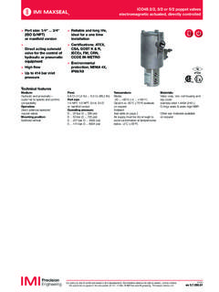
6 80 .. 1160,28241 NBR301-311P101-H0+13111+AYV1,10 .. 100 .. 1450,42242 NBR301-311P1011H0+63111+AYZ1,50 .. 60 .. 870,55242 NBR301-311P1015H0+63111+AYZ3210121212133 210121212133210133210133210133210133/2 NO ECI *4)0,80 .. 100 .. 1450,28242 NBR301-321P101-H0+631A1+AYZ1,10 .. 60 .. 870,42242 NBR301-321P1011H0+631A1+AYZ1,50 .. 30 .. 1020,55242 NBR301-321P1015H0+631A1+AYZ3221012101210 121332133213310121012101213321332133/2 UNI0,70 .. 60 .. 870,24242 NBR301-331P1070H0+63111+AYZ10 .. 3,50 .. 500,36242 NBR301-331P1010H0+63111+AYZ1,50 .. 20 .. 290,55242 NBR301-331P1015H0+63111+AYZ*1) Cv - Value in [gal/min] = kv x ; kv for 3/2 Uni valves represents flow value between ports 2 kv for 3/2 NC & 3/2 ECI valves represents flow value between ports 1 & 2 *2) valve equipped with Hit & Hold power saving electronic *3) valve models available with different nominal voltages *4) ECI - Push type version41 (46)AMP 2,8 x 0,514,217,215,220,79,78,27,4AA9,4M3M3 x 32,23,83213,8231 Dimensions2 ways standard1 Dimensions shown in mmProjection/First angleOur policy is one of continued research and development.
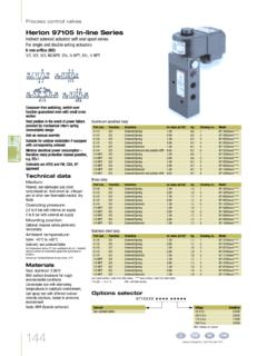
7 We therefore reserve the right to amend, without notice, the specifications given in this document. (2007 - 5019e) 2015 Fluid Automation Systems 15 mm MICROSOL Direct acting solenoid valveen ways 3,6 mm orifice3 ways standard23 Dimensions shown in mmProjection/First angle1 Sealing area2 The recommended mounting screw tightening torque is 0,6 0,1 Value in ( ) for ECI version4 O Rings 4 x 1 All solenoids are supplied with mounting screws and gasket or O ,76,9 3,3 3,321AA48 AMP 2,8 x 0,514,217,215,220,77,49,4M3M3 x 33,8249,78,23A211,93,83,83A41 (46)AMP 2,8 x 0,514,217,215,220,77,49,4M3M3 x 33,8231 FAS 15 mm MICROSOL Direct acting solenoid valveOur policy is one of continued research and development.
8 We therefore reserve the right to amend, without notice, the specifications given in this document. (2007 - 5019e) 2015 Fluid Automation Systems 01/16 DimensionsElectrical connector Model: plate Model: (Aluminium)Mounting plate Model: (Aluminium) Dimensions shown in mmProjection/First angleWarningThese products are intended for use in air, oxygen and neutral gas systems only. Do not use these products where pressures and temperatures can exceed those listed under Technical features .Before using these products with fluids other than those specified, for non-industrial applications, life-support systems, or other applications not within published specifications, consult IMI Precision Engineering, Fluid Automation Systems misuse, age, or malfunction, components used in fluid power systems can fail in various modes.
9 The system designer is warned to consider the failure modes of all component parts used in fluid power systems and to provide adequate safeguards to prevent personal injury or damage to equipment in the event of such failure. System designers must provide a warning to end users in the system instructional manual if protection against a failure mode cannot be adequately Produkte sind ausschlie lich mit Druckluft-, Sauerstoff- und neu- trale Gassysteme zu verwenden. Sie sind dort einzusetzen, wo die unter Technische Merkmale aufgef hrten Werte nicht berschritten werden.
10 Ber cksichtigen Sie bitte die entsprechende Katalogseite. Vor dem Einsatz der Produkte mit Fl ssigkeiten sowie bei nicht industriellen An-wendungen, in lebenserhaltenden- oder anderen Systemen, die nicht in den ver ffentlichten Anleitungsunterlagen enthalten sind, wenden Sie sich bitte direkt an IMI Precision Engineering, Fluid Automation Systems Missbrauch, Verschlei oder St rungen k nnen in Pneumatik-systemen verwendete Komponenten auf verschiedene Arten wird dringend empfohlen, die St rungsarten aller in Pneumatiksystemen verwendeten Komponententeile zu ber ck-sichtigen und ausreichende Sicherheitsvorkehrungen zu treffen, um Verletzungen von Personen sowie Besch digungen der Ger te im Falle einer solchen St rung zu verhindern.