Transcription of Fastener Handout - University of Wisconsin–Madison
1 Fastener Handout Introduction: Engineering Design Representation 2 Threads 2 Effect of thread angle on strength: 3 Standardization of Threads: 4 Descriptions of the Thread Series: 4 Class fit: 5 Specification of SAE/Metric Threads: 6 Local Notes (callouts) 8 Counterbore specification: 9 Countersink specification: 9 Writing notes for threaded holes: 10 Threaded Mechanical Fasteners 13 Examples of threaded hole notes 13 Clamping Force: 14 Cap Screws: 14 Machine Screws: 15 Set Screws.
2 15 Examples of Fastener specifications 16 Appendix A Fastener Head Dimension Tables 21 Appendix B Recommended Fastener Torques 28 Appendix C Bolt Grade Markings and Strength Chart 29 Appendix D Letter and Number Decimal Equivalents 31 2 Introduction: Engineering Design Representation Despite advances, 2D mechanical drawings are still the most popular format for design documentation. Automated extraction techniques allow mechanical drawings to be developed directly from 3D geometric models, simplifying the process.
3 However, some elements of design representation not easily conveyed through the model database and therefore not as easily extracted to 2D drawings. Many of these elements are notational in nature. Some examples include thread specifications, surface finishes, surface quality, and dimension tolerances. This Handout will focus on the standards of annotation for fasteners, and hole callouts (local notes). Annotation standardization is provided by the ASME Y14 series of standards. These standards call for the expanded use of symbology in annotation.
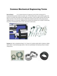
4 This is due to the international understandability of symbols. The table at right shows the current standard symbols commonly used in mechanical drawings along with the out-dated abbreviation form. We will discuss this topic further when covering Geometric Dimensioning and tolerance . Threads Screw threads serve three basic functions in mechanical systems; 1) to provide a clamping force 2) to restrict or control motion, and 3) to transmit power. Geometrically, a screw thread is a helical incline plane. A helix is the curve defined by moving a point with uniform angular and linear velocity around an axis.
5 The distance the point moves linear (parallel to the axis) in one revolution is referred to as pitch or lead. The term internal threads refers to threads cut into the sidewall of an existing hole. External threads refers to threads cut or rolled into the external cylindrical surface of a Fastener or stud. The size most commonly associated with screw threads is the nominal diameter. Nominal diameter is a more of a label than a size. For example, a bolt and nut may be described as being diameter. But neither the external threads of the bolt nor the internal threads of the nut are exactly.
6 500 in diameter. In fact, the bolt diameter is a little smaller and the nut diameter a little larger. But it is easier to specify the components by a single size designation since the bolt and nut are mating components. 3 Major Diameter - the largest diameter of the thread Minor Diameter - the smallest diameter of the thread Crest the peak of the thread for external threads, the valley of the thread for internal threads Pitch Diameter nominally the mean of the major and minor diameters Thread Angle The included angle between two adjacent thread walls.
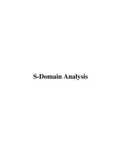
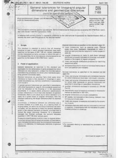
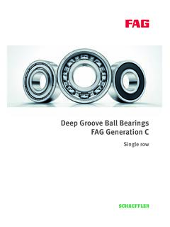
7 Effect of thread angle on strength: The lower the value of the thread angle, the greater the load carrying capability of the thread. The force of mating threads is normal to the surface of the thread. This is shown in the figure as F. The components of the force F transverse and parallel to the axis are shown as Ft and Fa. The component of force typically responsible for failure is that applied transverse to the axis of the thread. It is this load that can cause Fig. 1 Thread Profile (External) Fig. 2 Thread Forces 4 Fig. 3 Course, Fine Threads Fig.
8 4 Threads per Inch cracking in internal threads, especially under cyclic loads. internal threads are more susceptible since they are typically cut and cutting operations in metals produce surface irregularities that can contribute to crack growth. External threads are typically rolled onto a Fastener and therefore lack the surface flaws of cut threads. As the thread angle decreases, the component Ft gets smaller. This is why square and buttress threads are usually used for power transfer applications. Standardization of Threads: (Standard Inch Units) To facilitate their use, screw threads have been standardized.
9 In 1948, the United States, Great Britain and Canada established the current system for standard inch dimension threads. This is the Unified thread series and consists of specifications for Unified Coarse (UNC) Unified Fine (UNF) and Unified Extra Fine (UNEF) threads. Metric threads are also standardized. Metric thread specification is given through ISO standards. Thread information is available in tabular form from many sources including Mechanical Drawing texts and Machine Design handbooks. Thread form: Thread form is a classification based upon the cross-sectional profile of the thread.
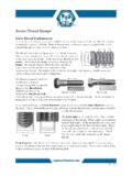
10 The standard thread form for inch unit threads in is the Unified (UN) thread form. This thread form is characterized by a 60 degree thread angle and a flat crest and rounded root. Thread series: Thread series is a standard based upon the number of threads/inch for a specific nominal diameter. Standards for standard inch units are: Coarse (C), Fine (F), Extra-Fine (EF). The figure at right shows fine and coarse thread fasteners. The designation is based upon the number of threads per unit length. A short discussion of each thread series is given below.