Transcription of Fasteners - University of Florida
1 1 EML2322L Design & Manufacturing Laboratory Fasteners Table of Contents I. Copyright Notice II. Why Care? 1. Definitions 2. Common Fastener Types 3. Fastener Nomenclature 4. Fastener Thread Types 5. Rolled Threads vs. Cut Threads 6. Fastener Function 7. Over-tightening vs. Under-tightening 8. Calculating Proper Fastener Torque 9. Fastener Designations 10. Fastener Choices 11. Tap Drills / Holes 12. Clearance Drills / Holes 13. Fastener Joint Design 14. Application Examples 2 Copyright notice: Much of the following material is taken from Carroll Smith s Nuts, Bolts, Fasteners and Plumbing Handbook. This book contains a wealth of knowledge concerning the proper selection and use of hardware used to join components. It is available for ~ $20 and will save you thousands of dollars in mistakes your first few years working industry. Translation: you would be foolish to perform mechanical design without reading a copy of this book from cover to cover! These notes attempt to establish a solid foundation and provide references for further study.
2 Additional material and tables come from K. H. Moltrecht s Machine Shop Practice and Joseph E. Shigley s Mechanical Engineering Design textbooks. Why you should care about these notes: Fastener failures (due to improper design/selection or installation) are THE NUMBER ONE cause of mechanical failures in industry. The topic is rarely given the focus it deserves in the classroom for a variety of reasons, none of which are acceptable. Consequently, this will likely be the most thorough discussion of Fasteners you will receive. Virtually every mechanical assembly designed in industry makes use of Fasteners to attach components together to form systems. 3 1. Definitions Fasteners are defined as hardware that can be easily installed and removed with hand or power tools. Common Fasteners include screws, bolts, nuts and rivets. The terms bolts and screws do not refer to specific types of Fasteners , but rather how they are used ( the application). Thus the same fastener may be termed a bolt or a screw.
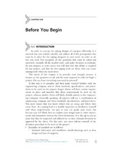
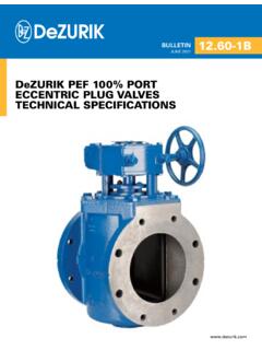
3 Bolts are defined as headed Fasteners having external threads that meet an exacting, uniform thread specification such that they can accept a non-tapered nut. Screws are defined as headed, externally-threaded Fasteners that do not mate with a non-tapered nut and are instead threaded into the material they will hold. As shown in figure 1, a bolt joint can be defined as that which uses a bolt and nut assembly (inherently requiring two tools to tighten or loosen) whereas a screw joint can be defined as one in which a screw is mated into a matching female thread in a workpiece (therefore only requiring one tool to tighten or loosen). As seen in figure 1, studs are a hybrid between a bolt and a screw, since one end of the stud functions as a screw while the other functions as a bolt. Figure 1. Bolt, screw and stud applications. 2. Common Fastener Types Figure 2 illustrates the variety of male Fasteners used in industry; the most common types are hex head, slotted head, flat (or countersunk) head, round head, socket (or allen ) head, button head and socket set screw.
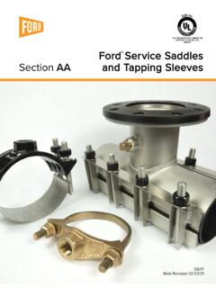
4 Figure 3 shows different female Fasteners ( nuts) used in industry; the most common types are regular hexagonal nuts and nylon ring elastic stop nuts (also known as lock nuts ).4 Figure 2. Male Fasteners common in industry. 5 Figure 3. Female Fasteners common in industry. 6 3. Fastener Nomenclature Design engineers are frequently tasked with selecting and specifying Fasteners used in their designs. Consequently, understanding basic fastener nomenclature is important. Figure 4 illustrates the different parts of a standard threaded fastener. Figure 4. Important male fastener nomenclature. A. major diameter the largest diameter of a fastener thread B. minor diameter the smallest diameter of a fastener thread C. pitch the linear distance from a point on the thread to a corresponding point on the next thread measured parallel to the axis of the thread D. lead the linear distance that a point on a fastener thread will advance axially in one revolution (equal to the pitch of the fastener) E.
5 Thread root the surface of the thread that joins the flanks of adjacent threads and is immediately adjacent to the cylinder from which the thread projects; in other words, the valley of the thread. F. thread crest the surface of the thread that joins the flanks of the thread and is farthest from the cylinder from which the thread projects; in other words, the peak of the thread. G. head the enlarged shape that is formed on one end of the fastener to provide a bearing surface and a method of turning (or holding) the fastener H. bearing surface the supporting surface of a fastener with respect to the part it fastens 7 I. point the extreme end of the threaded portion of a fastener J. shank the cylindrical part of a fastener that extends from the underside of the head to the starting thread K. length the axial distance between the bearing surface of the head and the extreme point L. grip length the length of the unthreaded portion of the fastener ( shank) measured axially from the underside of the bearing surface to the starting thread M.
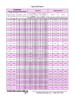
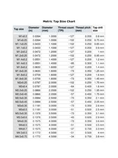
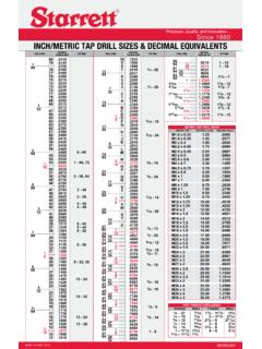
6 Thread length the length of the threaded portion of the fastener; NOTE: with all commercial and aerospace Fasteners , threaded length is a function of fastener diameter 4. Fastener Thread Types In the most general sense, there are two classes of fastener threads: English and metric. For each class, regardless of country of origin, there are two types of threads: fine thread and coarse thread. The drill and tap chart summarizes this information in one convenient location and will be referenced later in these notes. One of the most common fastener mistakes is using the wrong type of thread in the wrong type of material. The basic rule for fastener selection is: fine threads are stronger when the female thread is strong relative to the male thread, and coarse threads are stronger when the female thread is weak relative to the male thread. The reason for this statement is that a smaller minor diameter increases the thread area, resulting in higher static strength and fatigue resistance in female threads.
7 Conversely, a larger minor diameter increases the stress area, resulting in a higher static strength and fatigue resistance in male threads. It is instructive to select a fastener size off the tap chart and prove this statement; when performing the analysis, assume stresses are distributed over only the first five engaged threads. Figure 5 depicts a -20 fastener. Due to the elasticity of the fastener, only the first five threads are engaged during loading regardless of the thread type (coarse / fine). Female threads typically fail due to shear along the major diameter and male threads typically fail due to tensile loading along the thread root. 8 Figure 5. Thread engagement and fastener failure. Since five threads carry the entire load regardless of thread type, a decrease in the minor diameter increases the shear area and gives an advantage to the female threads while reducing the load carrying capability of the male fastener. Conversely, an increase in the minor diameter increases the male fastener s cross-sectional area and gives an advantage to the male fastener, however, this reduces the shear area and weakens the female threads.
8 Therefore, if the female fastener material is weak compared to the male fastener material, the female fastener should be given the advantage and coarse threads should be chosen. If the female fastener material is strong compared to the male fastener material, the male fastener will always fail first and should consequently be given the advantage by selecting fine threads. For this reason steel bolts and studs that thread into relatively weak aluminum or cast iron castings such as engine blocks, cylinder heads and gearboxes are always coarse threaded on the end that goes into the casting. Also invariably, the end of the stud that receives the nut is provided with a fine thread. In this way the designer ends up with the best of both worlds. Because coarse threads are faster to assemble, they are often used in applications where strength and weight are not of utmost concern. Conversely, virtually all aerospace bolted assemblies feature fine threads. Generally, unless threading into a relatively weak material, avoid coarse threaded Fasteners .
9 9 5. Rolled Threads Versus Cut Threads All quality Fasteners have rolled threads produced via rolling or sliding dies as seen in figure 6 or in this video on fastener manufacturing. Rolled threads (as opposed to threads cut on a lathe, with a cutting die or tap) produce superior surface finish (thus lower stress risers) and improved material properties from cold working the material, resulting in much higher fatigue resistance. Rolled threads increase thread strength by a minimum of 30% over well-cut Figure 6. Rolled threads. As illustrated in figure 7, when a thread is cut into a specimen, the grain flow of the material is severed. When a thread is rolled into a specimen, however, the grain flow of the material remains continuous and follows the contour of the thread. For this reason, rolled threads better resist stripping because shear failures must take place across the material grain rather than with it. Figure 7. Cut vs. rolled thread grain flow. 1 EBC Industries 10 As seen in figure 8, another benefit of thread rolling is it produces a much better surface finish than thread cutting.
10 The surface factor plot presented in figure 9 illustrates the relationship between stress concentrations and surface finish, which clearly shows that on high strength Fasteners , rolled threads possess up to twice the fatigue resistance compared to cut threads. Figure 8. Cut vs. rolled thread surface finish and thread profile. Figure 9. Surface finish modification factor as a function of fastener strength for rolled (polished) and cut (machined) threads. 11 Rolling also leaves the surface of the threads, particularly in the roots, stressed in compression. These compressive stresses must be overcome before the tensile stresses can reach a level that will cause fatigue failures. Compressive surface stresses also increase root hardness, further adding to the part's fatigue resistance. Improved fatigue strength resulting from the above factors is reported to be on the order of 50% - 75%. On heat-treated bolts from Rockwell C36 to 40 hardness that have threads rolled after heat-treatment, tests show increased fatigue strength of 5 to 10 times that of cut threads.