Transcription of FB2 - The TL431 in Switching Power Supplies - English
1 The TL431 in the Control of Switching Power SuppliesAgenda Feedback generalities The TL431 in a compensator Small-signal analysis of the return chain A type 1 implementation with the TL431 A type 2 implementation with the TL431 A type 3 implementation with the TL431 Design examples ConclusionAgenda Feedback generalities The TL431 in a compensator Small-signal analysis of the return chain A type 1 implementation with the TL431 A type 2 implementation with the TL431 A type 3 implementation with the TL431 Design examples ConclusionWhat is a Regulated Power Supply? Voutis permanently compared to a reference voltage Vref.
2 The reference voltage Vrefis precise and stable over temperature. The error, , is amplified and sent to the control input. The Power stage reacts to reduce as much as it = +-+-VinVoutRupperRlowerError amplifier - GVrefModulator - GPWMdPower stage - HVp +-+-VinVoutRupperRlowerError amplifier - GVrefModulator - GPWMdPower stage - HVp ControlvariableHow is Regulation Performed? Text books only describe op amps in The market reality is different: the TL431 rules!TL431optocouplererrVoutVI m the law!How do we Stabilize a Converter? We need a high gain at dc for a low static error We want a sufficiently high crossover frequency for response speed Shape the compensatorG(s)to build phase and gain margins!
3 M= 92 101001k10k100k1 Meg-180 0 -0 dB()Ts()Ts GM= 67 dB-88 ()67 TsdB= fc= kHzHow Much Phase Margin to Chose?0 Q 1Q= 5 Fast responseand no overshoot!Q< over dampingQ= critical dampingQ> under dampingAsymptotically stableQ= a Qfactor of (critical response) implies a mof 76 a 45 mcorresponds to a Qof : oscillatory response! phase margin depends on the needed response: fast, no good practice is to shoot for 60 and make sure malways > 45 Which Crossover Frequency to Select? crossover frequency selection depends on several factors: Switching frequency: theoretical limit is in practice, stay below 1/5 of Fswfor noise concerns output ripple: if ripple pollutes feedback, tail chasing can occur.
4 Crossover frequency rolloff is mandatory, in PFC circuits presence of a Right-Half Plane Zero(RHPZ): you cannot cross over beyond 30% of the lowest RHPZ position output undershoot specification: select crossover frequency based on undershoot specs2swF2outpcoutIVfC Vout(t)What Compensator Types do we Need? There are basically 3 compensator types: type 1, 1 pole at the origin, no phase boost type 2, 1 pole at the origin, 1 zero, 1 pole. Phase boost up to 90 type 3, 1 pole at the origin, 1 zero pair, 1 pole pair. Boost up to 180 101001k10k100k()Gs ()Gs270 boost125102050100 200500 1k()270Gs = ()Gs101001k10k100k()Gs ()
5 Gs270 boostType 1 Type 2 Type 3 Agenda Feedback generalities The TL431 in a compensator Small-signal analysis of the return chain A type 1 implementation with the TL431 A type 2 implementation with the TL431 A type 3 implementation with the TL431 Design examples ConclusionThe TL431 programmable Zener The TL431 is the most popular choice in nowadays designs It associates an open-collector op amp and a reference voltage The internal circuitry is self-supplied from the cathode current When the R node exceeds V, it sinks current from its cathode The TL431 is a shunt regulatorThe TL431 programmable Zener The TL431 lends itself very well to optocoupler 1biasbiasVIR=biasR RLED must leave enough headroom over the TL431 : upper limit!
6 LEDRFast laneSlow lanedc representationpullupRThe TL431 programmable Zener This LED resistor is a design limiting factor in low output voltages:431,min,maxmin,minCTRCTR outfTLLED pullupddCE satbiaspullupVVVRRVVIR + When the capacitorC1is a short-circuit, RLED fixes the fast lane gain()outVsLEDR pullupRddV1 IcI0 Vin ac()FBVs1()CTRFB pullupVsR I= 1()outLEDVsIR=()CTR()pullupFBoutLEDRVsVs R= This resistor plays a role in dc too!lowerR1 RThe TL431 the Static Gain Limit Let us assume the following design: , 20 LEDRmk + 431, min, satbiaspullupVVVVVVVVVmVImARk======== ,max857 LEDR >>> In designs whereRLED fixes the gain, G0cannot be below 17 dB You cannot amplify by less than 17 dBThe TL431 the Static Gain Limit You must identify the areas where compensation is ()argHs()Hs-17 dB500 500cfHz>okNot okRequires17 dB or moreRequiresless than 17 dB of gainTL431 Injecting Bias Current A TL431 must be biased above 1 mA to guaranty its parameters If not, its open-loop suffers a 10-dB difference can be observed!
7 Ibias= mAIbias= 300 A> 10-dB differenceEasysolutionIbiasRbias111biasR km== Agenda Feedback generalities The TL431 in a compensator Small-signal analysis of the return chain A type 1 implementation with the TL431 A type 2 implementation with the TL431 A type 3 implementation with the TL431 Design examples ConclusionTL431 Small-Signal Analysis The TL431 is an open-collector op amp with a reference voltage Neglecting the LED dynamic resistance, we have:LEDR lowerR1R()outVs1C1I()opVs()()()1outopLED VsVsIsR =()()()1111opoutoutupperuppersCVs V sV sRsRC= = 0() ()11111outLEDupperIs V sRsRC =+ We know that:1()CTRFB pullupVsR I= ()()11 CTR 1pullupupperFBoutLEDupperRsRCVsVsRsRC += TL431 Small-Signal Analysis In the previous equation we have:9a static gain9a 0-dB origin pole frequency9a zero We are missing a pole for the type 2!
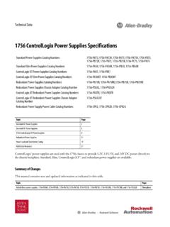
8 111zupperRC =11poupperCR =pullupR2C()FBVs0=CTRpullupLEDRGRddVAdd a cap. fromcollector to ground()()()112 CTR11pullupupperFBoutLEDupperpullupRsRCV sVsRsRCsRC + = + Type 2 transfer functionTL431 Small-Signal Analysis The optocoupler also features a parasitic capacitor it comes in parallel withC2and must be accounted forFBceRpullupCVddVFB(s)Vout(s)optocoupl erCopto2||optoCCC= TL431 Small-Signal Analysis The optocoupler must be characterized to know where its pole is21 Rpullup20kVdd53X1 SFH615A-44 VbiasRbiasVFB6 Vac5 Cdc10uFIcRled20kIF AdjustVbiasto have VFBat 2-3 V to be in linear region, then ac sweep The pole in this example is found at 4 kHz-3 dB()Os()
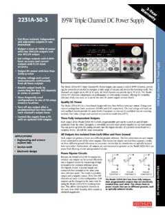
9 Os == Another designconstraint!4 kAgenda Feedback generalities The TL431 in a compensator Small-signal analysis of the return chain A type 1 implementation with the TL431 A type 2 implementation with the TL431 A type 3 implementation with the TL431 Design examples ConclusionThe TL431 in a Type 1 Compensator To make a type 1 (origin pole only) neutralize the zero and the pole()()()112 CTR11pullupupperFBoutLEDupperpullupRsRCV sVsRsRCsRC + = + 12upperpullupsRCsR C=12pullupupperRCCR=11 CTRpoupperLEDpullupRRCR =substitute2 CTRpoLEDCR =2 CTR2poLEDCfR = Once neutralized, you are left with an integrator()1poGss =()
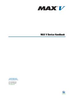
10 ||poccfGff=cpofcfGf=2 CTR2cfcLEDCGfR = TL431 Type 1 Design Example We want a 5-dB gain at 5 kHz to stabilize the 5-V converter431,min, satbiaspullupfccVVVVVVVVVmVImARkGfkHz=== ===== ===,max857 LEDR 728 LEDR= Apply 15% 5728cfcLEDCnFGfRk == Copto= 2 nF nF= = TL431 Type 1 Design Example SPICE can simulate the design automate elements = CoptoCTR = CTR5 RLED{RLED}2R2{Rupper}R310k6 Rpullup{Rpullup}Cpole{Cpole}Vdd{Vdd} = 1R5100mX1TL431_GB1 VoltageerrC1{C1}V(err)<0 ?0 : V(err) +Ibias*CTR*RpullupRmax=(A/B)*Rpullup*CTR R upper=( )/250ufc=5kGfc=-5G=10^(-Gfc/20)pi= *fcRpullup=20kRLED=Rmax* *Rpullup/RupperCpole1=CTR/(2*pi*Fpo*RLED )Cpole=Cpole1-CoptoFopto=4kCopto=1/(2*pi *Fopto*Rpullup)CTR = biaspoint selectionTL431 Type 1 Design Example We have a type 1 but dB of gain is missing?