Transcription of FCD LMAPS1331-01 Limitorque Actuation Systems
1 Actuation SystemsFCD LMAPS1331-01 (Replaces 130-50001)Motor Performance Data for Electric ActuatorsAccutronix MX and L120 SeriesFlow Control DivisionLimitorque Actuation SystemsFCD LMAPS1331-01 Motor Performance Data for Electric Valve Actuators3 Table of ContentsValve actuator control characteristics3 Standard motor design summary4 Power supply cable sizing4 Limitorque valve actuator motor performance data5MX actuators 208 volts, three-phase, 60 Hz6230 volts, three-phase, 60 Hz7380 volts, three-phase, 50 Hz8-9380 volts, three-phase, 60 Hz10-11400 volts, three-phase, 50 Hz12-13415 volts, three-phase, 50 Hz14-15460 volts, three-phase.
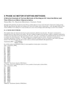
2 60 Hz16-17 575 volts, three-phase, 60 Hz18-19MX actuators low-temperature applications 380 volts, three-phase, 50 Hz20-21380 volts, three-phase, 60 Hz22-23400 volts, three-phase, 50 Hz24-25415 volts, three-phase, 50 Hz26-27460 volts, three-phase, 60 Hz28-29575 volts, three-phase, 60 Hz30-31L120 actuators 230 (208) volts, three-phase, 60 Hz32460 volts, three-phase, 60 Hz33575 volts, three-phase, 60 Hz34380 volts, three-phase, 50 Hz35400 volts, three-phase, 50 Hz36415 volts, three-phase, 50 Hz37 115 volts, single-phase, 60 Hz38 230 volts, single-phase, 60 Hz38 220 volts, single-phase, 50 Hz38 Flow Control DivisionLimitorque Actuation Systems4 Motor Performance Data for Electric Valve ActuatorsFCD LMAPS1331-01 Valve actuator control characteristics % of maximum load on motorOPEN% strokeCLOSE30100806040209080100002040608 0100% of maximum load on motor10080604020 OPEN% strokeCLOSE020406080100% of torque>10010080604020 Valve travel %Over torqueRequired torqueLarge motorNormal motorFigure 1 - Typical gate valve characteristicsFigure 2 - Typical plug, ball, and low-flow butterfly valvecharacteristicsFigure 3 - Effect of motor inertiaThe selection of valve actuator motors.
3 Motor protectiondevices, motor controls, and cabling requires an understanding of valve performance characteristics . Threecharacteristics that define valve requirements are: High starting torque Precise position control Intermittent operationHigh starting torqueFigures 1and 2illustrate typical valve performance by plotting motor load (torque) as a function of valve these figures it can be observed that the highest motortorque requirement occurs when the valve is in the closedposition. The dynamic torque required to move the valvethrough most of its travel is substantially lower. This hightorque at the closed position can be largely attributed to theengagement/disengagement of the valve seal.
4 The actual characteristic of the application can modifythese basic curves. For instance, high-flow butterfly valveswill exhibit an increased dynamic load. However, this is typically a transient condition and does not alter the basiccriteria for motor position controlElectric valve actuators automatically de-energize the motorto control valve position and output torque. The final valveposition or torque is therefore largely dependent on motorinertia. Motors that are too large for the valve will have toomuch inertia for the application. It will be difficult to regulatethe final valve position or torque as illustrated in Figure 3.
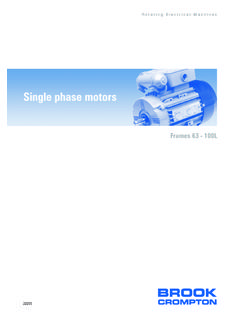
5 Inertia can be minimized by selecting a motor with theminimum frame size that is large enough to generatesufficient starting torque. The running torque requirementsare relatively low as explained above. Limitorque has foundthat the best combination of motor frame sizes results in a15-minute run time operationValves used in blocking or positioning service are infrequently operated and valve stroke times are normallylimited to a few minutes. Figure 4illustrates the thermalcharacteristics of a typical valve actuator motor and showsthat the 15-minute run time rating is adequate for mostvalves.
6 Exceptions include large, slowly operated valves orthose requiring frequent operation. These applications areaccommodated by special actuator selection Control DivisionLimitorque Actuation SystemsFCD LMAPS1331-01 Motor Performance Data for Electric Valve Actuators5 Temperature riseTime (seconds or minutes)100806040205 1015202530 Locked rotor (seconds)40% (minutes)20% (minutes)Figure 4 - Typical motor temperature rise characteristics of Limitorque valve actuator motorsOther considerations Thermal protection The use of Class F insulation andembedded thermal sensors provides motor protection fromhigh ambient temperature, high starting torque, and potential motor overload.
7 Enclosure Actuator motor designs are TENV (Totally Enclosed Non-ventilated) to protect againstenvironmental extremes. All enclosures are suitable forNEMA 4 and 6 (IP 67 and 68) service and can be XP(explosionproof) if of other valve typesSluice gates and guillotine dampers are examples of valvesthat require a continuous high running torque as opposed tothe types previously discussed. The torque requirement forthe sluice gate and guillotine damper types are application-dependent, and the data given in the accompanying tablesmay not be suitable for their selection. Please consultLimitorque for application assistance in the selection of actuators for these motor design summary High starting torque greater than the unseating torquerequirement Running torque 20% of the unseating torque Low inertia Run time rating 15 minutes Totally enclosed frame design Class F insulation Embedded thermal protectionPower supply cable sizingThe voltage at the actuator terminals must be maintained towithin 10% of the rated value for the motor to develop thespecified torque.
8 This is particularly important under startingand seating conditions that apply when beginning theopening or unseating phases. Assuming that the mainsprovide the rated voltage, this means that no more than 10% of the supply voltage can be dropped by the cable, connections, and any intervening protection or disconnectdevices when the motor is drawing locked-rotor switch and overload protectionThe rating of disconnect switches and motor overload protection devices is generally subject to national or localregulations, which should always be Control DivisionLimitorque Actuation Systems6 Motor Performance Data for Electric Valve ActuatorsFCD LMAPS1331-01 Limitorque valve actuator motor performance dataThis bulletin contains data for L120 and MX series valveactuators.
9 The terms used in these tables are defined below: Actuator speed the output speed of the actuator in revolutions per minute (RPM) when the motor is deliveringits rated torque. Rated torque for valve actuator applications, this is typically the torque required by the actuator when the valveis moving and is defined as 20% of nominal rotor rated torque loads greater than 20%, please contactLimitorque. Full-load current the current drawn by the motor when itis delivering rated torque. Locked-rotor current the steady-state current drawn bythe motor when the rotor is stationary and rated voltageand frequency are applied.
10 This is the current required bythe actuator when the valve is unseating. Rated motor speed the motor speed required to producethe rated output speed of the actuator. hp (horsepower) the power (expressed in horsepower)produced by the actuator motor when it is running at ratedspeed and delivering rated torque. kW (kilowatts) the power (expressed in kilowatts)produced by the actuator motor when it is running at rated speed and delivering rated torque (1 kW = hp). Efficiency the ratio of the output power delivered to theactuator to the input power of the motor when the actuatoris operating at rated speed and torque.