Transcription of Features
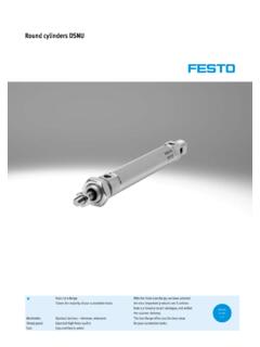
1 5401525 - REV G 6/19 page 1 OF 6potter electric Signal Company, LLC St. Louis, MO Tech Support: 866-956-0988 / Customer Service: 866-572-3005 SeriesOutside Screw and Yoke Valve Supervisory SwitchDescriptionThe OSYSU is used to monitor the open position of an OS&Y (outside screw and yoke) type gate valve. This device is available in two models; the OSYSU-1, containing one set of SpDT (Form C) contacts and the OSYSU-2, containing two sets of SpDT (Form C) contacts. These switches mount conveniently to most OS&Y valves ranging in size from 2 to 12 (50mm to 300mm). They will mount on some valves as small as (12,5mm). The cover is held in place by two tamper resistant screws that require a special tool to remove. The tool is furnished with each device. TestingThe operation of the OSYSU and its associated protective monitoring system shall be inspected, tested, and maintained in accordance with all applicable local and national codes and standards and/or the authority Having Jurisdiction (manufacturer recommends quarterly or more frequently).
2 A minimum test shall consist of turning the valve wheel towards the closed position. The OSYSU shall operate within the first two revolutions of the wheel. Fully close the valve and ensure that the OSYSU does not restore. Fully open the valve and ensure that the OSYSU restores to normal only when the valve is fully Specifications DimensionsSee Fig 8 Weight lbs (0,73 kg)enclosureCover: Die Cast Finish: Red powder CoatBase: Die Cast Finish: Black powder CoatAll parts have corrosion resistant finishesCover TamperTamper Resistant ScrewsOptional Cover Tamper Switch availableContact RatingsOSYSU-1: One Set of SpDT (Form C)OSYSU-2: Two Sets of SpDT (Form C) amps at 125/250 amps at 30 VDC Resistive10 mamps minimum at 24 VDCenvironmental Limitations-40 F to 140 F (-40 C to 60 C)NeMa 4X (Ip 65) and NeMa 6p (Ip 67) enclosure (Use suitably rated conduit and connector)Indoor or Outdoor Use (See OSYSU-eX Bulletin 5400705 for Hazardous locations)Conduit entrancesTwo Knockouts for 1/2 conduit provided (See Notice on page 6 and Fig.)
3 9 on page 5)Service UseNFpa 13, 13D, 13R, 72 Features NeMa 4X* (Ip 65) and 6p (Ip 67) *Enclosure is 4X. For additional corrosion protection of mounting hardware, use model OSYSU-2 CRH -40 to 140 (-40 C to 60 C) operating temperature range Visual switch indicators Two conduit entrances adjustable length trip rod accomodates up to 12aWg wire Three position switch detects tampering and valve closure Knurled mounting bracket prevents slipping Fine adjustment feature for fast, easy installation RoHS compliant One or two SpDT contact models (-1,-2)Important: This document contains important information on the installation and operation of OS&Y valve supervisory switches. please read all instructions carefully before beginning installation. a copy of this document is required by NFpa 72 to be maintained on subject to change without noticeClose the valve fully to determine that the stem threads do not activate the switch.
4 The switch being activated by the stem threads could result in a false valve open any work is done on the fire sprinkler or fire alarm system, the building owner or their authorized representative shall be notified. Before opening any closed valve, ensure that opening the valve will not cause any damage from water flow due to open or missing sprinklers, piping, - REV G 6/19 page 2 OF 6potter electric Signal Company, LLC St. Louis, MO Tech Support: 866-956-0988 / Customer Service: 866-572-3005 SeriesOutside Screw and Yoke Valve Supervisory SwitchTheory of OperationThe OSYSU is a 3 position switch. The center position is the normal installation position. Normal is when the switch is installed on the OS&Y valve, the valve is fully open and the trip rod of the OSYSU is in the groove of the valve stem. Closing the valve causes the trip rod to ride up out of the groove and activates the switches.
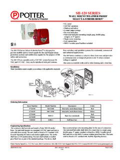
5 Removing the OSYSU from the valve causes the spring to pull the trip rod in the other direction and activates the Switch Status IndicationThere are 3 visual indicators to determine the status of the switches. Fig 1; the actuator button of the micro switches are on the raised section of the switch 2; the trip rod is perpendicular to the base and lined up with the alignment mark on the mounting 3; the white visual indicator is visible through the window on the back of the switch actuator. A final test is to meter the contacts marked COM and to ensure they are an open circuit when the valve is open and that they close and have continuity within 2 revolutions of turning the valve handwheel towards the closed position and the contacts remain closed as the valve is completely closed and until the valve is completely opened when the trip rod drops back into the groove in the valve 1 Fig 2 Fig 3 Trip Rod Locking ScrewFig 4 Fig 5 Micro-adjustment Feature5401525 - REV G 6/19 page 3 OF 6potter electric Signal Company, LLC St.
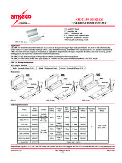
6 Louis, MO Tech Support: 866-956-0988 / Customer Service: 866-572-3005 SeriesOutside Screw and Yoke Valve Supervisory SwitchSmall Valve Installation NOTE: If the valve stem is pre-grooved at 1/8 minimum depth; proceed to step Remove and discard "e" ring and roller from the trip With the valve in the FULL OpeN position, locate the OSYSU across the valve yoke as far as possible from the valve gland so that the spring loaded trip rod of the OSYSU is pulled against the non threaded portion of the valve stem. position the OSYSU with the bracket near the handwheel as shown in Fig. 6 if possible to avoid creating a pinch point between the wheel and the Loosen the locking screw that holds the trip rod in place and adjust the rod length (see Fig. 5). When adjusted properly, the rod should extend past the valve screw, but not so far that it contacts the clamp bar. Tighten the locking screw to 5 in-lbs minimum to hold the trip rod in place and properly seal the enclosure.
7 NOTE: If trip rod length is excessive, loosen the locking screw and remove the trip rod from the trip lever. Using pliers, break off the one (1) inch long notched section (see Fig. 10). Reinstall trip rod and repeat Step 3 Mount the OSYSU loosely with the carriage bolts and clamp bar supplied. On valves with limited clearance use J-hooks supplied instead of the carriage bolts and clamp bar to mount the Mark the valve stem at the center of the trip Remove the OSYSU. Utilizing a 3/16 or 1/4 diameter straight file, file a 1/8 minimum depth groove centered on the mark on the valve stem. Deburr and smooth the edges of the groove to prevent damage to the valve packing and to allow the trip rod to move easily in and out of the groove as the valve is operated. NOTE: a groove depth of up to approximately 3/16 can make it easier to install the OSYSU so that it does not restore as it rolls over by the threads of the valve Mount the OSYSU on the valve yoke with the spring loaded trip rod of the OSYSU pulled against the valve stem and centered in the groove of the stem.
8 If possible, position the OSYSU with the flat side of the bracket toward the hand wheel, as shown in Fig. 6, to help avoid creating a pinch point between the wheel and OSYSU. When in this preferred mounting position, it is usually best to use the white indicator visible through the window, as illustrated in Fig. 3, to aid in initially locating the OSYSU in the correct position on the yoke. If the unit must be installed inverted with the white indicator no longer easily visible, use the visual indicators of the actuator buttons on the micro-switches, as illustrated in Fig. 1, or the trip rod alignment mark on the bracket, as illustrated in Fig. 2 , to aid in initially locating the Final adjustment can be made by slightly loosening the two screws on the bracket and using the fine adjustment feature (see Fig. 5). The adjustment is correct when the plungers on the switches are depressed by the actuator and there is no continuity between the COM and NO terminals on the Tighten the adjustment screws and all mounting hardware securely (20 in-lbs minimum).
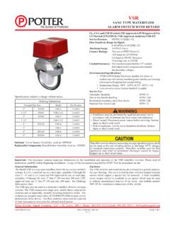
9 Check to insure that the rod moves out of the groove easily and that the switches activate within two turns when the valve is operated from the FULL OpeN towards the CLOSeD position. 10. Reinstall the cover and tighten the cover screws to 15 in-lbs minimum to properly seal the Valve Installation - 1/2 Through 2 1/2 SizesFig 6 AMOUNTING BRACKETBFLAT SCREWDRIVERMICROADJUSTMENTFEATURECENTER LINE ON RODROLLERSLOTTED MOUNTINGHOLES MAY BE USEDFOR FINE ADJUSTMENTOF SWITCH ASSEMBLYTO MOUNTING BRACKETDETAIL A SCALE 1 : 1 LEVERS ARE SHOWNIN "SETTING" POSITIONWITH ROLLER LOCATEDIN THE GROOVE ON THEACME THREAD SHAFTDETAIL B SCALE 1 : 1 WHITE LINE THROUGH THERECTANGULAR WINDOWINDICATES "SETTING" POSITIONWITH ROLLER LOCATED IN THEGROOVE ON THE ACME THREADSHAFTS lotted mounting holes and micro-adjustment feature may be used for fine adjustment of switch assembly to mounting bracket. Re-tighten screws to 20 in-lbs the valve fully to determine that the stem threads do not activate the switch.
10 The switch being activated by the stem threads could result in a false valve open - REV G 6/19 page 4 OF 6potter electric Signal Company, LLC St. Louis, MO Tech Support: 866-956-0988 / Customer Service: 866-572-3005 SeriesOutside Screw and Yoke Valve Supervisory SwitchClose the valve fully to determine that the stem threads do not activate the switch. The switch being activated by the stem threads could result in a false valve open BRACKETBFLAT SCREWDRIVERMICROADJUSTMENTFEATURECENTER LINE ON RODROLLERSLOTTED MOUNTINGHOLES MAY BE USEDFOR FINE ADJUSTMENTOF SWITCH ASSEMBLYTO MOUNTING BRACKETDETAIL A SCALE 1 : 1 LEVERS ARE SHOWNIN "SETTING" POSITIONWITH ROLLER LOCATEDIN THE GROOVE ON THEACME THREAD SHAFTDETAIL B SCALE 1 : 1 WHITE LINE THROUGH THERECTANGULAR WINDOWINDICATES "SETTING" POSITIONWITH ROLLER LOCATED IN THEGROOVE ON THE ACME THREADSHAFTL arge Valve Installation NOTE: If the valve stem is pre-grooved at 1/8 minimum depth; proceed to step With the valve in the FULL OpeN position, locate the OSYSU across the valve yoke as far from the valve gland as possible so that the spring loaded trip rod of the OSYSU is pulled against the non threaded portion of the valve stem.