Transcription of Features and Application - Conesys
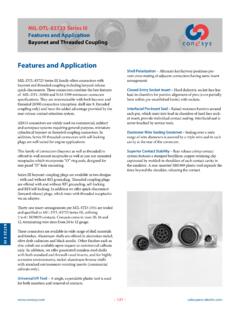
1 MIL-DTL-38999. Features and Application Series I. Features and Application Closed-Entry Socket Insert Hard dielectric socket face has lead-in chamfers for positive alignment of pins (even partially bent within pre-established limits) with sockets. 38999 S I. MIL-DTL-38999 Series I is a bayonet coupling subminiture configuration with high contact density, ideal for smaller wire Interfacial Pin Insert Seal Raised moisture barriers gauge, general-purpose applications. These environment- around each pin, which mate into lead-in chamfers of hard resisting connectors are 100% scoop-proof. Pins are face socket insert, provide individual contact sealing. recessed in elongated shells to prevent the possibility of Interfacial seal is never touched by service tools. bending contacts when plugs are scooped into the mating receptacles.
2 Elastomer Wire Sealing Grommet Sealing over a wide range of wire diameters is assured by a triple wire seal in This family of connectors is offered in 5 receptacle-mounting each cavity at the rear of the connector. styles. They include square flange receptacles, for both front and rear panel (wall) mounting; square flange receptacles, for Superior Contact Stability Rear release crimp contact both front and rear box mounting; and jam nut receptacles system Features a stamped beryllium-copper retaining clip which incorporate O ring seals, designed for rear panel captivated by molded-in shoulders of each contact cavity in D hole mounting. the insulator. A rear-inserted M81969 plastic tool expands the tines beyond the shoulder, releasing the contact. Standard plugs provide RFI protection by incorporating a continuous strip of attached grounding fingers attenuating Shell Polarization Alternate key/keyway positions prevent interference up to 1 GHz.
3 Cross mating of adjacent connectors having identical insert arrangement. Fifty-seven insert arrangements per MIL-STD-1560 are tooled and qualified to MIL-DTL-38999 Series I, utilizing 2 to 128 contacts. Contacts come in sizes 22M, 22D, 20, 16, 12, and 8 (coax and twinax), terminating wire sizes from 28. gauge to 12 gauge including coaxial cable. These connectors are available in wide range of shell materials and finishes. Aluminum shells are offered in electroless nickel, olive drab cadmium and bright cadmium. Other finishes such as anodic and zinc cobalt are available upon request to commercial callouts only. In addition, we offer passivated stainless steel shells with standard environment-resisting inserts (commercial callouts only), and for highly corrosive environments, nickel-aluminum-bronze shells with standard environment-resisting inserts (commercial callouts only).
4 Universal I/R Tool A single, expendable plastic tool is used for both insertion and removal of contacts. Scoop-Proof Design Recessed pins in elongated shells minimize the possibility for contact damage. In a blind mating Application , mating shells cannot scoop the pins, and cause a shorting or bending of contacts. 3 MIL-DTL-38999. Performance Specifications Series I. Performance Specifications Shielding Effectiveness RFI and EMI attenuation at the specified frequencies meet Operating Temperature Range the requirements of MIL-DTL-38999. RFI shielding effectiveness of mated connectors with 38999 S I. Finish B: -65 C to +175 C (-85 F to +347 F). Finish F: -65 C to +200 C (-85 F to +392 F RFI backshells is measured in a triaxial radio frequency Finish A: -65 C to +150 C (-85 F to +302 F) leakage fixture. EMI shielding effectiveness is measured at the interface Material and Plating Data (Finish) of mated connectors and tested by the mode-stirred B aluminum shell, olive drab cadmium over nickel base technique specified in method 3008 of MIL-STD-1344.)
5 F aluminum shell, electroless nickel finish A aluminum shell, silver to light iridescent yellow color Shock and Vibration Requirements (bright) cadmium over electroless nickel Wired, mated connectors shall not be damaged, nor shall there be a current interruption longer than one microsecond Corrosion Resistance when subjected to the following: Finishes A and B withstand 500-hour salt spray. Finish F withstands 48-hour salt spray. Standard Shock Mated connectors withstand a pulse of approximate half Durability sine wave of 300 G 15 percent magnitude with duration of Minimum of 500 mating cycles 3 1 milliseconds applied in three axes per MIL-STD-1344, method 2004. Environmental Seal Wired, mated connectors with specified accessories at- High Impact Shock tached, shall meet the altitude-immersion test specified in When mounted as specified in MIL-S-901, grade A, a drop MIL-DTL-38999.
6 Of a 400 lb. Hammer from 1 foot, 3 feet and 5 feet applied to connector in three axes, totaling nine impacts. Fluid Resistance connectors resist specified immersions in MIL-PRF-7808, Vibration MIL-PRF-23699, MIL-PRF-5606, M2-V Chevron oil, Coolanol Mated connectors , with proper accessories, withstand the 25, MIL-DTL-83133 (JP-8), MIL-DTL-5624 (JP-4, JP-5), following vibration levels: SAE-AMS1424 Type I, and other solvents and cleaning agents. Sine Vibration per MIL-STD-202, method 204, test condition G. Shell-to-Shell Conductivity Random Vibration per MIL-STD-1344, method 2005, Finish F = millivolt maximum potential drop test condition V and test condition VI, Letter J at ambi- Finishes A and B = millivolts maximum potential drop ent temperature. Voltage Rating Suggested Operating Voltage Test Voltage Test Voltage Test Voltage Test Voltage (Sea Level) Sea Level 50,000 Ft.
7 70,000 Ft. 100,000 Ft. Service Rating AC (RMS) DC V RMS V RMS V RMS V RMS. M 400 550 1300 550 350 200. N 300 450 1000 400 260 200. I 600 850 1800 600 400 200. II 900 1250 2300 800 500 200. exactly what peak voltages, switching currents, transients, Note: The establishment of electrical safety factors is left etc., can be expected in a particular circuit. entirely to the designer, as he is in the best position to know 4 MIL-DTL-38999. Part Number Development Series I. Military and aero - electric Part Number Development Mil. Prefix MS 27467 T 13 B 35 P A. aero Prefix AE 167 T 13 B 35 P A -340. 38999 S I. Shell Type 27466 = Front, wall mount receptacle = 166 ( aero p/n). 27467 = RFI grounding plug = 167 ( aero p/n). 27468 = Jam nut receptacle = 168 ( aero p/n). 27496 = Front, box mount receptacle = 196 ( aero p/n). 27505 = Rear, box mount receptacle = 105 ( aero p/n).
8 27656 = Rear, wall mount receptacle = 156 ( aero p/n). Class T = With acc. thread (MS27466, MS27467, MS27468 & MS27656). E = Same as T in line above but is not approved for new design (E-nut is not included). = No acc. thread, box mount (MS27496 & MS27505). Shell Size 9, 11, 13, 15, 17, 19, 21, 23 or 25. Finish (Material & Plating). A = Aluminum shell, silver to light iridescent yellow color (bright) cadmium over nickel base B = Aluminum shell, olive drab cadmium over electroless nickel base F = Aluminum shell, electroless nickel finish S = Stainless steel shell, passivated ( aero p/n only). Insert Arrangement See page 19 thru 21. Contact Style P = Pin S = Socket A = Pin connector less pins (with intent to use non-standard pin contacts). B = Socket connector less sockets (with intent to use non-standard socket contacts).
9 Polarization (Keying). N = Normal (Omitted in part number). A, B, C, or D (B & C keyways are not available in shell size 9). Modification (applies to aero part numbers only). 01 = Less contacts (is not marked on the part). 340 = Connector kitted with M85049/27-XXX E-nut 341 = Connector kitted with M85049/49-2-XXX straight clamp 342 = Connector kitted with M85049/47 XXX right angle clamp Consult factory for other modifications Note 1: Each connector is furnished with contacts unless Note 2: Proper part number marking has no 0 in front ordered less contacts (L/C) as follows: One spare contact for of single digit shell size (9) and no 0 in front of single digit inserts requiring 1 through 26 of each contact and two spares layout. Example of each: J MS27466T9B35S and for inserts with more than 26 contacts and a minimum of J MS27466T11B5S.
10 In both, N for normal is omitted. In one sealing plug up to 10% of the number of contacts. Spare addition, J or JAN must now be marked in front of the MS. Coax and Twinax contacts are not supplied. One insertion/ part number. removal tool for each contact size is also included. 5 MS27466. Front, Wall Mounting Receptacle AE166. Bayonet Coupling, Crimp Removable, Rear Release, Scoop-Proof ( ). MAX. A. 38999 S I. D F. MASTER KEYWAY. B .219( ). MIN. FULL THREAD..060( ). MAX GROMMET EXTENSION. H. E MAX. GROMMET. J ACCESSORY TEETH. G ACCESSORY THREAD. 4X MINOR KEYWAYS. 4x C. BLUE COLOR BAND. Page 5 Completed Part Number Page 15 Contacts, Sealing Plugs and Tools Pages 19 21 Insert Arrangements Page 4 Performance Specifications Pages 16-18 Insert Availability and Contact Information Page 13 Polarization A B C D E F G H J.