Transcription of FEATURES - dlpdesign.com
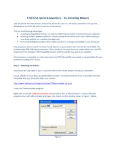
1 Rev (April 2018) 1 DLP design , Inc. DDLLPP--RRFFSS11228800 DDAATTAA RRAADDIIOO ** PRELIMINARY DOCUMENT-SUBJECT TO CHANGE ** FEATURES : x Operation x + Output Power x 4+ Mile Range (Line of Sight) x Antenna Connector for External Antenna x LORA, GFSK and FLRC Modulation Modes x On-Board Chip Antenna x FCC/IC/RED/MIC (Japan) Modular Approvals in Place x Single Power Supply x Development Kit Available x Demonstration Source Code Available for Use with the NUCLEO-L073RZ microcontroller development board (purchased separately) APPLICATION AREAS.
2 X Real-Time Security x Body-Worn Medical Telemetry x Battery-Powered Home Automation x Electric/Water/Gas Automated Meter Reading x Industrial Monitoring and Control x Active RFID x Long Range, Battery-Powered, Multi-Hop Sensor Networks INTRODUCTION The DLP-RFS1280 is a low-cost module for transmitting and receiving digital data via radio frequency. All of the DLP-RFS1280 s electronics (including an antenna) reside on a single PCB, and all operational power is derived from a single supply voltage. The transceiver design consists of a Semtech SX1280 low-power, integrated UHF transceiver and an antenna switch for selecting between the on-board chip antenna and an optional external antenna.
3 The hardware is designed for maximum range and optimal battery life. Rev (April 2018) 2 DLP design , Inc. ELECTRICAL SPECIFICATIONS Supply Voltage Frequency Range Output Power 14mW (+ ) Maximum (Conducted) TX/RX Range Greater than 5 Miles (Antenna-Type Dependent) Protocol Multiple Communications Interface SPI Operational Power Transmit 24mA Operational Power Receive Depending Upon the Operating Mode Operational Power Sleep 8uA (Deepest Sleep Mode) Antenna Connector * Operating Temperature 0-70 C *Please see the Antenna Section for important regulatory details.
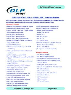
4 IO PINS IO Pin Definitions 1 GROUND 2 NRESET 3 BUSY 4 DIO1 5 DIO2 6 DIO3 7 MISO_TX 8 GROUND 9 POWER SUPPLY 10 MOSI_RX 11 SCK_RTSN 12 NSS_CTS 13 ANTSEL 14 GROUND Rev (April 2018) 3 DLP design , Inc. MECHANICAL MECHANICAL DRAWING - Overall Dimensions: x x In. Note: thou = mils or inches. MOUNTING OPTIONS The DLP-RFS1280 module can be either surface mounted to a printed circuit board or connected using spaced headers ( posts).
5 Rev (April 2018) 4 DLP design , Inc. APPLICATION DEVELOPMENT Demonstration source code written in the C programming language is available for free download upon purchase of the DLP-RFS1280 or DLP-RFS1280 ACT demonstration platform. The code was developed using MBED and Keil uVision for the STMicrocontroller Nucleo microcontroller development module. Source code for the demonstration software has been developed for the STM32L073RZ-based Nucleo board.
6 Compiling the L073 source code may require the user to purchase the Keil compiler. Additional information on the operation of the Semtech SX1280 transceiver IC is available in the datasheet for the SX1280. DEMONSTRATION HARDWARE - EDK This section describes how to operate the DLP-RFS1280 ACT demonstration hardware (purchased separately). The DLP-RFS1280 ACT includes a DLP-RFS1280 transceiver module that allows the user to easily verify normal operation of the transceiver and assists in helping them become familiar with the operational firmware.
7 Rev (April 2018) 5 DLP design , Inc. Note: Flow diagrams for the demonstration code can be found at the end of this datasheet. Source code for the demonstration EDK is made available upon purchase of the DLP-RFS1280 or DLP-RFS1280 ACT. Power for this test platform can be provided by a phone charger battery (purchased separately) or a PC USB port using the included USB cable. The USB connector is a 5-pin, mini-USB connector. For normal mode, press the RESET button.
8 The system will be in Receive Mode waiting for packets to arrive. After each mode listed below, press RESET to return to idle state before proceeding to the next test mode. TEST MODE: For Carrier Wave (CW) Mode - No Modulation Press Button 1 until LORA Mode is selected: Press and hold Button 1. While holding Button 1, press and release RESET. Continue to hold Button 1 until you hear a beep. Release Button 1, and the system will be transmitting at on the internal chip antenna with no modulation. - Be sure to turn the volume up (blue knob next to the speaker) if you cannot hear the beep.
9 - You can change to the external antenna by pressing Button 2 (ANT SEL). The display will show either a C for chip antenna or a W for whip antenna. - You can change the carrier frequency to by pressing Button 5 (LMH). Repeatedly pressing the LMH button will cycle through low ( ), medium ( ) and high ( ) carrier frequencies. TEST MODE: For CW Mode - With Modulation - LORA Mode Press Button 1 until LORA Mode is selected: Press and hold Button 3. While holding Button 3, press and release RESET. Continue to hold Button 3 until you hear a beep.
10 Release Button 3 and the system will be transmitting at on the internal chip antenna with LORA modulation. Rev (April 2018) 6 DLP design , Inc. TEST MODE: For CW Mode - With Modulation - FLRC Mode Press Button 1 until FLRC Mode is selected: Press and hold Button 3. While holding Button 3, press and release RESET. Continue to hold Button 3 until you hear a beep. Release Button 3 and the system will be transmitting at on the internal chip antenna with FLRC modulation.