Transcription of February 2018 0-10 V Control Topology - Lutron …
1 0-10 V Control TopologyApplication Note #587 Revision EFebruary 20181 Customer Assistance V Topology is a common Control Topology that can be found all across the lighting industry. It was originally developed for Control of fluorescent ballasts, but in the growing market of LEDs, it has become one of the most common Control topologies. While there are some standard details to how 0-10 V works as a Topology , there are many details that can affect the quality of the end solution. 0-10 V Topology is often looked at as an open Topology and that 0-10 V products work together without any issues. As the industry expands and advances, this logic becomes flawed. There are a number of details that can determine how a 0-10 V solution should be designed and how well a solution will work. This document will provide a summary of these details for the varying Lutron 0-10 V products, as well as provide background and explanation of different 0-10 V , it is important to note that even after all of these details have been collected and examined to determine the compatibility between a 0-10 V ballast / driver and a Control , there is no guarantee that the dimming performance will be of high quality.
2 Dimming performance is ultimately limited by the quality and design of the ballast / driver. For these reasons, Lutron recommends EcoSystem ballasts / drivers. For more details, see the How can Lutron EcoSystem technology alleviate the issues that exist with 0-10 V Topology ? of ContentsLutron Equipment .. 2 Lutron Equipment Detail Explanations .. 30-10 V vs. 10-0 V vs. 1-10 V .. 3 Sink vs. Source .. 30-10 V mA Rating.. 5 Relay Rating .. 5 NEMAR 410-2011 Rating (National Electrical Manufacturers Association) .. 6 Linear vs. Logarithmic Dimming .. 7 Other Technology Considerations .. 11 Inrush Current .. 11 Emergency Lighting .. 12 Polarity of Low-Voltage Wiring .. 13 Class 1 vs. Class 2 Wiring .. 13 Dimming Curves .. 14 FAQs .. 15 How can I guarantee compatibility between the 0-10 V Control and ballast / driver? .. 15 How far can I run a low-voltage 0-10 V circuit?
3 15 How many fixtures can I put on a 0-10 V Control circuit? .. 16 What do I do if the load is not called out as NEMAR 410-2011 compliant? .. 16 Can I run 0-10 V wires with line voltage wires? .. 17 Can I Control a 0-10 V circuit without a relay? .. 17 What voltage do the 0-10 V controls sit at in the off position?.. 17 What happens to the 0-10 V signal if the controller loses power and the ballast / driver does not? .. 17 What if I want the 0-10 V device to Control another load type? .. 18 How can Lutron EcoSystem technology alleviate the issues that exist with 0-10 V Topology ?.. Note #587 Lutron EquipmentTable 1: Lutron 0-10 V DevicesInput SignalOperating Voltage (V~) Control CapabilityRelay Rating (A)0-10 V Line Rating (mA)Sink / SourceLinear vs LogarithmicNEMAR 410-2011 CompliantDIN Power Module (LQSE-4T5)QS link1200-10 V5 A each 20 A total50 Auto sink /sourceLinearYe sPowPak dimming module with 0-10 V controlClear Connect wireless120-2770-10 V560 Auto sink /sourceLinearYe sVive PowPak dimming module with 0-10 V controlClear Connect wireless120-2770-10 V860 Auto sink /sourceLinearYe sPowPak wireless fixture controller (FCJ-010)Clear Connect wireless120-2770-10 V16 Auto sink /sourceLinearYe sEnergi Savr Node for 0-10 V (QSN)QS link120-2770-10 V, 10-0 V1650 SinkLinearYe sInternational Energi Savr Node for 0-10 V (QSNE / LQSE)QS link220-2400-10 V, 10-0 V1050 Auto sink /sourceLinearNo 5 TVM module (GRX-TVM)
4 Panel load240-10 V, 10-0 V16 150 Auto sink /sourceLinearYes 2 EcoSystem to 0-10 V interface (TVI-LMF-2A)EcoSystem120, 220/240, 2770-10 V225 SinkLinearYe s0-10 V Control interface (GRX-TVI)Forward, Reverse, Center 3100-2770-10 V16300 SinkLinearYe sNova T* controls (NTSTV) 120-2770-10 V830 SinkLogarithmicYe sDiva 0-10 V controls (DVSTV) 120-2770-10 V850 SinkLinearYe sDiva 0-10 V controls (DVSTV-453) 120-2770-10 V450 W (120 V~) (277 V~)50 SinkLinearYe sDiva 0-10 V controls (DVTV) 24 V-0-10 V16 (with PP-DV)30 SinkLogarithmicYes 4 Maestro 0-10 V dimmer sensor (MS-Z101) 120-2770-10 V850 SinkSelectableYe s1 Depending on the panel type, 16 A is the maximum for a single circuit. Uses panel modules to switch line Both X modules and U modules are NEMAR 410-2011 rated. 3 Need either high / low-end trim or 3-wire fluorescent PP-DV is NEMAR 410-2011 compliant and is assumed to be switching the load in this Rated for resistive, inductive, or capacitive loads as defined by IECR / EN Assistance Note #587 Lutron Equipment Detail Explanations0-10 V vs.
5 10-0 V vs. 1-10 V0-10 V is a Topology defined by the International Electrotechnical Commission (IECR) 60929 Annex E standard and uses a varying DC voltage between 1 and 10 V to determine the lighting level. The fixture outputs a minimum light level below 1 V. It is not defined whether this is off or low-end, which means you can get differing functionality depending on the manufacturer. Between 1 and 10 V, the signal corresponds to levels between the minimum and maximum output level. A signal above 10 V corresponds to the maximum light level. Sometimes it is referred to as 1-10 V, as that is the actual range in which the light levels will V is a Topology that is not defined in the IECR standard, but it also makes use of a varying DC voltage. The levels are inverse of a 0-10 V Topology , with 10 V being low-end and 1 V being high-end. This Topology was made popular in certain metal halide dimming systems, but has almost disappeared as a result of the decline of metal halide as a high output light vs.
6 SourceThe concept of sink vs. source in 0-10 V Topology relates to the small amount of current being provided on the 0-10 V channel that is used to drive the circuit and create the DC voltage difference. When looking at the Control and the ballast(s) / driver(s) being used in a particular application, one will always be providing the current (source), and one will be dissipating it (sink). In order for the Control and the ballast / driver to be able to work together, you must have one device that can source and one that can sink, allowing for a complete circuit to exist between the devices. There are some devices that are capable of being sink or source (often by auto sink / source detection) which allow them to take either role. As a note, there can sometimes be issues if connecting two auto sink / source devices together. Depending on how the devices perform their auto-detect, they might continue to misread each other and create issues with using Lutron EcoSystem devices, the sinking and sourcing of low-voltage current is taken care of as part of the EcoSystem definition.
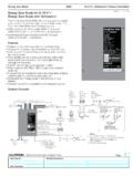
7 This will continue to hold true as Lutron maintains a review of all products (by Lutron or other manufacturers) that are part of the EcoSystem on next Note #587 Lutron Equipment Detail Explanations (Continued)Sink vs. Source (Continued)IECR 60929 Ballast Control StandardThis standard dictates that the ballast shall be the source of the current and the Control should sink that current. Not all ballasts / drivers use this standard, so it is important to determine whether the ballast / driver is sink or source so that a matching Control can be selected. The IECR 60929 standard is the standard most commonly applied in commercial and residential applications. American National Standards Institute (ANSIR) Ballast / Driver Control StandardThis standard is very similar to the IECR 60929 standard in that the ballast / driver is called out as the source and the Control as the 1: Ballast / Driver as SourceANSIR Entertainment Lighting Control StandardWritten by the Entertainment Services and Technology Association (ESTA), this standard was specifically designed around theatrical lighting Control .
8 In this standard, the Control is the source and the ballast / driver is the sink. This standard is usually only used with legacy devices because the DMX standard has become the most commonly used Control standard within the theatrical 2: Control as SourceControl(Sink)Current+ + Ballast / Driver(Source) Control (Source)Current+ + Ballast / Driver(Sink)5 Customer Assistance Note #5870-10 V mA RatingDirectly related to the previous notes on sink vs. source, every 0-10 V device has a rating for how much current (in mA) that it sources or sinks. In addition to stating that the ballast shall source the current, the IECR 60929 standard dictates a minimum ballast source current of 10 A and a maximum of 2 mA. Not all ballasts / drivers follow this standard (2 mA maximum), but it can be used as an approximation if no information can be determined about the ballast / driver being the sinking / sourcing capabilities of the Control and the ballast / driver are necessary to determine the maximum number of ballasts / drivers that can be controlled by a single Control circuit.
9 The maximum number of ballasts / drivers can be found by taking the sink capability of the Control and dividing by the source current of each ballast / driver. The mA rating and the relay rating are the two limiting factors for how many ballasts / drivers can be used with a Control . With LED lamps, it is very common for the mA rating to be the limiting using Lutron EcoSystem devices, the limit for the low-voltage communication loop is based on the number of device addresses. The current needed to run the low-voltage circuit is already accounted for in the address RatingThe rating of the relay is the traditional current rating that is discussed with regards to switching controls ( , 16 A relay). It represents the total amount of power that can be run through the Control device to power the total load of the connected fixtures. It is very common to see a rating of 16 A because that is the maximum allowable current that a 20 A lighting circuit can have (the NECR mandates a deration to 80% for lighting circuits).
10 The mA rating and the relay rating are the two limiting factors for how many ballasts / drivers can used with a Control . With fluorescent loads, it is very common for the relay rating to be the limiting using Lutron EcoSystem devices, a relay is not required because EcoSystem ballasts / drivers are capable of electronic Equipment Detail Explanations (Continued)Continued on next Note #587 Lutron Equipment Detail Explanations (Continued)NEMAR (National Electrical Manufacturers Association) 410-2011 RatingNEMAR 410-2011 is a voluntary testing standard that defines inrush current limit. It was developed soon after fluorescent dimming ballasts were introduced to the market. The lamp and dimmer manufacturers agreed to create the testing standard to manage inrush currents. High inrush current is also a concern for LED lamps and can often be the limiting factor over steady state current of how many LED lamps can be part of a Control circuit.