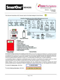
Transcription of Fenwal Controls DETECT-A-FIRE® Detection and Release …
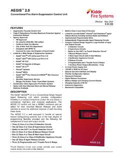
1 F-12-0-001 June 20201 FEATURES Repeatable - self-restoring, nothing to replace, testable Versatile - various temperature settings available Durable - long lasting stainless steel shell Economical - wide spacings reduce installation costs Factory set Internal contact area hermetically sealed in stainless steel shell ROHS CompliantAPPLICATIONS Protection of schools, factories, offices, libraries, or other non-residential buildings Power generation Gas station islands Paint spray booths Range hoods Engine compartmentsDESCRIPTIONDETECT-A- fire (D-A-F) detectors are the "heart" of many fire protection systems. The highly reliable D-A-F has been the standard forover 75 years. The D-A-F is used for signaling overheat or fire conditions.
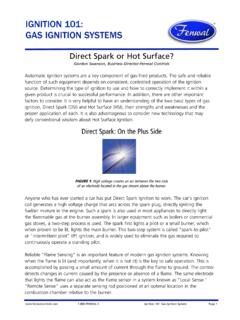
2 In the vast majority of applications, the D-A-F provides the ini-tial heat sensing that is used to activate suppression systems using clean agent , CO2, inert gases, wet or dry chemicals or detectors are widely accepted, because they are designed with rate compensation. This provides a unique advantage over bothfixed temperature and rate-of-rise types of detectors because the D-A-F detector accurately senses the surrounding air temperatureregardless of the fire growth rate. At the pre-determined set point, the system is temperature detectors must be completely heated to alarm temperature and therefore a lag in response time may occur with a fastrate fire . Rate-of-rise devices, on the other hand, are triggered by the rate of increase in ambient temperature and are subject to falsealarms caused by harmless, transient thermal gradients such as the rush of warm air from process key to the detector's sensitivity is in the design (Figure 1).
3 The outer shell is made of a rapidly expanding alloy which closely followschanges in surrounding air temperature. The inner struts are made of a slower expanding alloy. Designed to resist thermal energyabsorption and sealed inside the shell, the struts follow temperature changes more slow rate fire (Figure 2) will heat the shell and struts together. At the "set point", the detector will trigger, actuating the alarm or releasingthe transient rush of warm air up to 40 F/min. may expand the shell, while not triggering the detector. By ignoring transient warm air excur-sions, the D-A-F detector virtually eliminates false alarms prevalent with rate-of-rise a fast rate fire (Figure 3) starts, the shell will expand rapidly. The struts will close, actuating the alarm and/or releasing the agent .
4 Thefaster the fire rate of growth, the sooner the D-A-F detector will react. Figure 1. Ready Figure 2. Slow fire Figure 3. Fast FireDETECT-A- fire Detection and Release DevicesEffective: June 20202F-12-0-001 VERTICAL DETECT-A- fire DETECTOR SPECIFICATIONSV ertical D-A-F detectors are designed for use in both "ordinary" or "hazardous" locations. For "ordinary" use, they may be mounted toany approved junction box with 7/8" diameter opening by using 1/2-14 NPT mounting nuts. The device may be wired in or out of con-duit, depending on local preferences and codes. To facilitate supervision of system wiring, four lead wires are provided on normally openvertical detectors (that close on temperature rise).
5 When mounted in a appropriately classified mounting box ( Figure 7), detectorsare Underwriters Laboratory and Underwriters Laboratory of Canada listed, and FM Approved for hazardous MODELST able 1: Model Numbers 27121, 28021, 27120*, 28020* FSetting FTolerance CSetting CToleranceSpacing (in feet)RTIC olor CodingUL ULC FM140+7/-860+4/-550 50 20 V-Fast Black160+7/-871+4/-525 25 20 V-Fast Black190+7/-888+4/-550 50 25 V-Fast White210+7/-899+4/-525 50 25 V-Fast White225+7/-8107+4/-525 50 25 V-Fast White275 10135 625 50 25 V-Fast Blue325 10163 650 50 25 V-Fast Red360 10182 825 50 30 V-Fast Red450 15232 1025 50 30 V-Fast Green500** 15260 1050 50 30 V-Fast Orange600** 20316 12N/A 50 30 V-Fast Orange725** 20385 12N/A 50 30 V-Fast OrangeNotes.
6 For clean agents or CO2 suppression systems, ceiling spacing is 20ft. apart unless otherwise specified. For NFPA Guidelines on ceiling height compensation, see Table 7. *27120 and 28020 are normally closed devices and do not meet the requirements of NFPA-72 for use as initiating devices (they are 2-wire devices). *27120 and 28020 are not listed by FM with RTI. ** Not available for Normally Closed detectorsTable 2: Vertical D-A-F SpecificationModel NumberHead MaterialContact OperationElectrical Rating(Resistive Only)27120-0 BrassNormally Closed(Open on Rise) Amps 125 Amps 125 VDC27120-22 Stainless Steel27121-0 BrassNormally Open(Close on Rise) Amps 125 Amps 125 Amps 24 Amps 48 VDC27121-20 Stainless Steel28020-3 Stainless SteelNormally Closed(Open on Rise) Amps 125 Amps 125 VDC28021-5 Stainless SteelNormally Open(Close on Rise) Amps 125 Amps 125 Amps 24 Amps 48 VDC12-200001-00X*Approximate weight: 5 oz.
7 All shell material is Stainless Steel. All Stainless Steel is Type 300.* Specialty product with limited 4. Hexagonal HeadFigure 5. Coupling HeadEffective: June 20203F-12-0-001 HORIZONTAL DETECT-A- fire DETECTOR SPECIFICATIONSH orizontal D-A-F detectors are designed for locations where appearance is a factor. The low-profile, functional designlends physical protection of the detector while making it suitable for commercial, industrial, mercantile public buildings,institutions, and marine applications in non-hazardous locations (those classified as "ordinary" under the National ElectricCode). Flush mounted detectors are designed to fit standard 4-inch octagonal electric boxes and surface mounting detec-tors are designed to mount directly on ceilings or on 4-inch electrical junction boxes.
8 Canadian Electrical Codes requiresmounting only to an electrical junction ModelsTable 3: Model Numbers: 27021-0, 27021-1, 27020-0*, 27020-1* FSetting FToleranceSpacing (in feet)RTIC olor CodingUL ULC FM140 +7/-8 505020 Quick Black160 +7/-8 252520 Quick Black190 +7/-8 505025 Fast White210 +7/-8 255025 Fast White225 +7/-8 255025 Fast White275 10 255025 Fast Blue325 10 505025 Fast Red *27020-0 and 27020-1 are normally closed devices and do not meet the requirements of NFPA-72 for use as initiating devices (they are 2-wire devices). *27020-0 and 27020-1 are not listed by FM with 4: Horizontal D-A-F SpecificationsModel Number Mounting Style Contact OperationElectrical Rating(Resistive Only)27020-0 Flush MountNormally Closed (Open on Rise) Amps 125 Amps 125 VDC27020-1 Surface Mount27021-0 Flush MountNormally Open(Close on Rise) Amps 125 Amps 125 Amps 24 Amps 48 VDC27021-1 Surface MountApproximate weight: 10 6.
9 Horizontal DetectorsNote:Horizontal D-A-F detectors are equipped with connector blocks in place of : June 20204F-12-0-001 HORIZONTAL AND VERTICAL DETECT-A-FIREDETECT-A- fire MOUNTINGD-A-F detectors are not position sensitive. Horizontal and vertical detectors refer to the most common mounting configuration for that detector. However each type can be mounted either horizontally or vertically depending on the application and installation 5: D-A-F Response Time Index (RTI) and SpacingModel OperationTemperature(Set Point)Response TimeIndex (ft-s) 1/2 RTIC lassificationRTI RatedSpacingOld RatedSpacing27021-0 HorizontalFlush MountNormally Open(Close on Rise)140 F (60 C), 160 F (71 C)110 Quick(20 X 20) ft(6 x 6) m(25 x 25) ft(8 x 8) m27021-1 HorizontalSurface Mount27021-0 HorizontalFlush MountNormally Open(Close on Rise)190 F (88 C), 210 F (99 C), 225 F (107 C), 275 F (135 C), 325 F (163 C)140 Fast(25 x 25) ft(8 x 8) m(25 x 25) ft(8 x 8) m27021-1 HorizontalSurface Mount27121-0 VerticalBrass HeadNormally Open(Close on Rise)140 F (60 C), 160 F (71 C), 190 F (88 C), 210 F (99 C), 225 F (107 C), 275 F (135 C), 325 F (163 C), 360 F (182 C), 450 F (232 C)
10 , 500 F (260 C), 600 F (316 C), 725 F (385 C)99 (140 F, 160 F)148 (190 F, 210 F,225 F, 275 F, 325 F,360 F, 450 F, 500 F,600 F, 725 F)V-Fast(30 X 30) ft(9 x 9) m(25 x 25) ft(8 x 8) m27121-20 VerticalStainless Head28021-5 Vertical StainlessCoupling HeadNote: Spaces shown are distances between detectors on smooth ceilings, the distances from partitions or walls would be half that shown. Authority Having Jurisdiction (AHJ) should be consulted before 6: Mounting and Hazardous Location ClassModel Number(Vertical Only)Hazardous LocationFitting required for UL & ULC Listing and FM Approval27120-227121-2028020-328021-5 Class I, GroupsA, B, C and D;Class II, GroupsE, F and GMount detector to a suitable listed fitting in accordance with National Electric Code and/or local authority having I, GroupsB, C and D.