Transcription of Fiber Bandwidth - meridian-tech.com
1 Multimode vs. Singlemode Fiber Bandwidth We continue this series of articles on Fiber optic facts and applications with a discussion of Fiber Bandwidth and its impact on transmission distance for high- Bandwidth /data rate video channels. There is a general misconception that once you transmit signals on Fiber , the distance is almost unlimited because the Fiber 's Bandwidth is, for all practical purposes, infinite and attenuation is low. The reality is that, while singlemode Fiber has an extremely high Bandwidth , multimode Fiber has limited Bandwidth characteristics that significantly influences the maximum distance that you can transmit high resolution/definition video signals. Multimode Fiber suffers from a physical characteristic termed modal dispersion or differential mode delay. The term multimode Fiber is derived from the fact that the core of the Fiber will support hundreds of different optical paths for the light to traverse from one end of the Fiber to the other, each with its own propagation time.
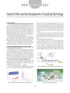
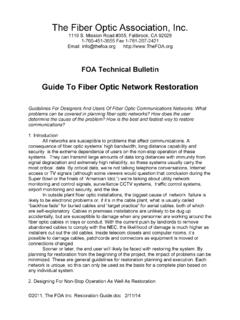
2 The figure below illustrates this principle. (Courtesy: The Light Brigade). As the light travels down the Fiber the difference between the times the various modes' or paths of light reach the end of the Fiber will continue to increase. This graphic shows several modes taking different paths and how the time differential between these paths results in the optical pulse being spread over time. This phenomenon is referred to as modal dispersion and is generally the limiting factor in transmitting high speed data over multimode Fiber . Contrary to some beliefs, the many modes in a multimode Fiber are not used to transmit individual wavelengths or signals but simply refer to the different paths the SAME signal pulse traverses as it travels down the Fiber . The number of different optical paths is related to the core diameter of the Fiber , the wavelength and spectral or wavelength spread of the light source. Multimode Fiber 's Bandwidth is a function of both the type of multimode Fiber and the wavelength of the LED or LASER light source used to transmit the signals.
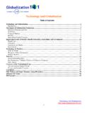
3 The larger the Fiber 's core and shorter the light source's wavelength, the more modes or paths the Fiber will support. In the last article, we mentioned two different types of multimode Fiber 50/125um and Fiber , each with its own unique Bandwidth characteristics. These fibers are also available in a version termed laser-optimized which provides higher Bandwidth characteristics for use with higher speed laser sources for specific wavelengths. The table below gives a range of the various fibers'. Bandwidth as a function of core diameter and wavelength. Multimode Legacy Laser Optimized Legacy Laser Optimized ( m) ( m) (50/125 m) (50/125 m). Fiber Type Wavelength 850nm 160 200-500 500 1000-2000. Bandwidth * 1300nm 500 500 600-1000 500. (MHz-km). There are a number of fibers from different manufacturers each with its own Bandwidth characteristics. The numbers shown here represent a range of Fiber bandwidths available from these various manufacturers. 700 Elmont Rd, Elmont, NY 11003, Tel: 516-285-1000; Fax: 516-285-6300.
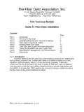
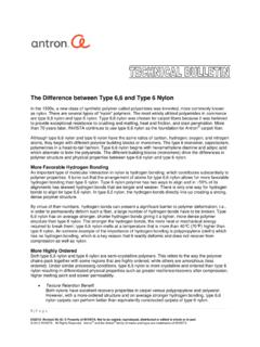
4 The Bandwidth of the Fiber is inversely proportional to the distance. For example, if the Fiber has a Bandwidth of 500 MHz-km, the Bandwidth of the Fiber at a distance of 1km will be 500 MHz. At 2km, the Bandwidth will have been reduced to 250 Mhz and at 5km, the overall Bandwidth of that same Fiber will now be 100 MHz. Let's take an example of a simple HDSDI data stream at a nominal data rate of This signal has an effective Bandwidth of approximately 750 Mhz. If we assume that the Bandwidth of the Fiber must be greater than or equal to the Bandwidth of the signal being transmitted, from the table above, we can approximate the following maximum distances over the various multimode Fiber types: Fiber type Wavelength Transmission distance (approx.). 850nm 200 meters Legacy m 1300nm 660 meters 850nm 660 meters Legacy 50/125 m 1300nm 1000 meters 850nm 2500 meters Laser Optimized 50/125 m 1300nm 660 meters Obviously, as the data rate increases for other real-time video signals such as DVI, RGBHV & HDMI, these distances over multimode Fiber are reduced even further.
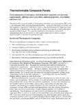
5 One way to increase the distance of these high data rate signals over standard (legacy) multimode Fiber is to use a technique called wavelength division multiplexing. Using this concept, each of the signal's colors (red, green, blue). and sync are transmitted on different wavelengths using different lasers. Using an optical multiplexer, these optical signals are combined and transmitted down a single multimode Fiber . In this way, the data rate of each signal is nominally reduced by a factor of three, allowing for a distance of approximately three times that of the same signal if it were transmitted using only one wavelength. This wavelength multiplexing is a very common method for increasing the number of signals and the effective data rate over a single Fiber . With the use of proper lasers, singlemode Fiber , on the other hand, has essentially unlimited Bandwidth for these applications. Distances in excess of 50km (30 miles) are possible for even the highest video data rate signal.
6 Singlemode Fiber will generally be loss limited. That is, the signal will run out of available light at the end of the Fiber before the optical dispersion of the Fiber significantly impacts the Bandwidth (or quality) of the signal. The singlemode Fiber 's counterpart to modal dispersion in multimode Fiber is called chromatic dispersion. This arises from the principle that different wavelengths of light travel at different speeds down the singlemode Fiber . If only one wavelength were to be transmitted, the chromatic dispersion would be essentially zero and the Fiber 's distance would be limited strictly by its attenuation. However, practical narrow spectral width lasers generally emit several closely-spaced wavelengths. Depending on the wavelength, this will lead to some level of chromatic dispersion thus limiting the distance of even singlemode fibers. There are other aspects of Fiber and laser characteristics that go into a properly designed optical system. It is up to the optical system engineer to properly match the Fiber type, Fiber distance and laser type/wavelength to ensure that it will accommodate the maximum signal data rate that needs to be transmitted.
7 These short articles are meant to provide you with enough information to help you become informed about the characteristics of Fiber transmission and make more knowledgeable decisions as you move toward implementing Fiber in your future systems. Our next topic in the Feb '09 issue will provide an overview of various Fiber optic test equipment and test techniques. Being able to properly verify and troubleshoot a Fiber system is key to ensuring a viable, high-reliability system. After this topic, we will continue with various Fiber and system level components as well as reviewing a variety of applications. If you have any questions or if you have any particular Fiber topic you would like to know more about, please send an email to me at (Published in SCN Magazine, Jan '09). 700 Elmont Rd, Elmont, NY 11003, Tel: 516-285-1000; Fax: 516-285-6300.