Transcription of FIBER OPTIC CABLE ASSEMBLY …
1 FIBER OPTIC CABLE ASSEMBLY manufacturability AND design GUIDE A. INTRODUCTION The purpose of this document is to define the standards and guidelines that should be followed in order to fabricate a harsh environment FIBER OPTIC CABLE ASSEMBLY . Environmental requirements such as temperature, humidity, vibration, shock, etc., should be communicated to the CABLE ASSEMBLY manufacturer for compliance considerations and adjustments. Most materials identified in this guide are qualified in a military or harsh environment. Deviations from these standards and guidelines should be discussed with the manufacturer. B. DIMENSIONING AND TOLERANCING 1. Standard CABLE ASSEMBLY Length Tolerances CABLE Length (feet) Tolerance < 5 *min + inches > 5 to 50 +5% / -0 > 50 to 100 +4% / -0 >100 to 250 +3% / -0 >250 to 500 +2% / -0 >500 +1% / -0 Table 1 NOTES: Tolerances can be rounded up to the nearest inch or foot for simplicity when cables are long.
2 Tolerance requirements less than inches should be discussed with the manufacturer. 2. Length of Overall ASSEMBLY Unless otherwise specified, the final overall length of a CABLE ASSEMBLY shall be measured or determined from end to end as illustrated below. a) Single terminus/connector to single terminus/connector Ferrule tip to ferrule tip. Follow Table 1 Figure-1 1 b) Multi-channel connector (plug/receptacle) to pig-tail (fan-out) Front face of the insert cap on multi-channel connector to ferrule tips of individual connectors. 2" HEAT SHRINK2" HEAT SHRINKF ollow Table 1 Figure-2 c) Multi-channel connector (plug/receptacle) to multi-channel connector (plug/receptacle) Front face of the insert cap on one multi-channel connector to the other.
3 Follow Table 1 Figure-3 2" HEAT SHRINK12"(+2"/-0") 3. Length of Breakouts (fan-out) Length: 12 inches is typical but it can be specified. Tolerance: + inches / inch is typical. If the pig-tail length exceeds the typical length, use the tolerances in Table 1. Figure-4 2 4. Length of Breakout Behind Plug/Receptacle 2 " HEAT SHRINK6"(+/-1") Length: 6 inches is standard. Tolerance: +/- inch is typical. Dimension lines shall be placed at the edge of the heat shrink. Figure-5 C. LABELING REQUIREMENTS 1. Types a) Heat shrink tubing: Polyolephyn, MIL standard M23053. Standard colors are WHITE and YELLOW. NOTE: Part number of M23053 heat shrink tubing shall be M23053/5-XXX-Y XXX = size/diameter Y = color (4 = yellow, 9 = white) b) Label wrap: Clear plastic sheet with adhesive backing.
4 This type is used for label repair/replacement. The most common are Brady brand DAT-38-292 or Panduit LJSL8-PO3-1. c) Flag: Used mostly on 900 m buffered cables (EX: Brady M71FT-1-425). d) Other: Other labeling material options are available upon request. 2. Label Length Standard/default length is 2 inches (reference), as produced by most label manufacturers. Label length is governed by the label manufacturer. 3. Marking Details Marking details are based on MIL-STD-130 and will be legible and permanent. a) Marking information example Cage code = 0 YPM2 for AFSI, part number = 2006112209MD-01, serial number with date code embedded. The info can be provided in any order, and two lines of info are recommended.
5 0 YPM2 2006112209MD-01 SN: YYDDDXXXX NOTES: - YY = Last two digits of year. - DDD = Day of year. - XXXX = Sequence number from 0001 to 9999. 3 b) Character size Character height of inches is the default. Maximum number of characters per line is 22 to 25. Different character heights may be used for specific applications so that information fits into the available space on the label. All marking shall be legible or free from smears and smudges. c) Number of lines of information In general, 1 to 2 lines of marking information are preferred on any label. 1 line of marking information is strongly recommended for labels installed on simplex CABLE . d) Location Labels shall be located within 10 inches from the back of the connector or a distance that satisfies manufacturability .
6 Standard tolerance shall be +/- inches; however, the tolerance should be as loose as possible or specified as located approximately. 2" HEAT SHRINK4"(+/-2") Figure-6 CABLE ASSEMBLY pig-tails (fan-out) labels will be referenced from the tip of connectors. Standard tolerance shall be +/- inches; however, the tolerance should be as loose as possible. 2 " HEAT SHRINK6"(+/-3") Figure-7 CABLE ASSEMBLY lengths less than 6 feet shall utilize 1 label/marker for identification. Avoid placing label/marker in the middle of a CABLE ASSEMBLY that is longer than 6 feet, especially when the CABLE is spooled onto a reel. 4 When a CABLE ASSEMBLY cannot be physically labeled, marked, or tagged due to inadequate space (extremely short ASSEMBLY or CABLE diameter is too small, 900 m buffered FIBER ), the label shall be applied to the bag or container that contains the ASSEMBLY .
7 Flag labels may also be considered. e) Orientation Unless otherwise specified or defined on the drawing or purchase order, orientation of the identification label/marker shall be flexible. Example: the text can be read toward or away from the connector end. If marking orientation is required, it shall be specified on the drawing. f) Permanency Marking should not smear when lightly rubbed with finger or with a Q-tip soaked in isopropyl alcohol. D. CABLE ACCESSORIES 1. Standard Types a) Furcation Tubing This tubing provides protection for 250um or 900um buffered FIBER and serves as a sub-unit or jacket similar to a breakout CABLE . Typical sizes are mm, mm and mm. b) Expando Wrap This is the preferred method for CABLE management and protection with high flexibility and ruggedness.
8 It is recommended for cabinets and shelters when short runs are utilized (< 50 ft). The most common material is polyester with sizes/diameters ranging from to 1 inch and above. Example: 674900252 (1/4 , BEGP-0500 (1/2 ), BEGP-0750 (3/4 ). 5 c) Spiral Wrap This wrap is good for CABLE management, providing protection and flexibility. The most common materials are polyester and nylon, with typical sizes/diameters ranging from to 1 inch and above. Example: NSW-1/4 (1/4 ), NSW-1/2 (1/2 ). This option can be costly because the installation is labor intensive. d) Convoluted/Corrugated Tubing This tubing is good for CABLE protection but less flexible than those mentioned previously. Various materials are available (PTFE, Nylon, PEEK, etc.
9 And typical sizes/diameters range from to 1 inch and above. Metallic tubing is not recommended because kinks in the tubing can cause damage to the FIBER or CABLE . 6 e) Lacing Tape This tape is good for CABLE management, but it provides no protection. The most common material is polyester braided, waxed, per MIL-T 43435B, TYPE II. f) Heat Shrink This accessory is typically used in conjunction with types a) through e). The most common types are M23053/4 and M23053/5. g) Flexible Boots Flexible boots are a good accessory to use for strain relief at the back of various connector types. Several boots are also used to create Y or T breakouts within CABLE assemblies. The main manufacturer is Raychem/Tyco.
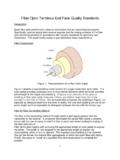
10 7 E. COMPATIBILITY REQUIREMENTS 1. FIBER Sizes and CABLE Types a) FIBER Sizes Multiple FIBER sizes exist in the FIBER OPTIC world. The same FIBER core size should be used to minimize optimize optical parameters such as insertion loss and return loss. Some circumstances, such as mode conditioning, warrant connecting different FIBER sizes. The most common FIBER sizes are listed below. Multimode FIBER ( m) Single Mode FIBER (9/125 m) CoreCladdingMultimode FIBER (100/140 m) Multimode FIBER (50/125 m) b) CABLE Types Three main CABLE types are typically chosen for harsh environments: simplex FIBER , breakout FIBER , and distribution FIBER . Simplex FIBER (sub- CABLE ) and Breakout CableThis type of CABLE is typically used with receptacle style connectors and naval plug style connectors.