Transcription of Fiber Optic Sensors and Their Applications …
1 5th International Advanced Technologies Symposium (IATS'09), May 13-15, 2009, Karabuk, Turkey Fiber Optic Sensors AND Their Applications . Fidanboylu, , * , and Efendio lu, H. a, *. Fatih University, Istanbul, Turkey, e-mail: b Fatih University, Istanbul, Turkey, e-mail: Keynote Address Abstract detection of the losses increasing, one could sense changes in phase, intensity, and wavelength from outside Beside advantages; recent advances, and cost reductions perturbations on the Fiber itself. Hence Fiber Optic sensing has stimulated interest in Fiber optical sensing. So, was born [2]. researchers combined the product outgrowths of Fiber Optic telecommunications with optoelectronic devices to emerge In parallel with these developments, Fiber Optic sensor Fiber Optic Sensors . Numerous researches have been technology has been a significant user of technology conducted in past decades using Fiber Optic Sensors with related with the optoelectronic and Fiber Optic different techniques.
2 Intensity, phase, and wavelength communication industry [3-7]. Many of the components based Fiber Optic Sensors are the most widely used sensor associated with these industries were often developed for types. In this paper, an overview of Fiber Optic Sensors and Fiber Optic sensor Applications . Fiber Optic sensor Their Applications are presented. technology in turn has often been driven by the development and subsequent mass production of Keywords: Fiber optics, optical Fiber sensing, Fiber Bragg components to support these industries. As component gratings (FBGs), interferometry, microbending, smart prices have decreased and quality improvements have structures been made, the ability of Fiber Optic Sensors to replace traditional Sensors have also increased. 1. Introduction Fiber Optic Sensors are excellent candidates for monitoring With the invention of the laser in 1960's, a great interest in environmental changes and they offer many advantages optical systems for data communications began.
3 The over conventional electronic Sensors as listed below: invention of laser, motivated researchers to study the Easy integration into a wide variety of structures, potential of Fiber optics for data communications, sensing, including composite materials, with little interference and other Applications . Laser systems could send a much due to Their small size and cylindrical geometry. larger amount of data than microwave, and other electrical Inability to conduct electric current. systems. The first experiment with the laser involved the Immune to electromagnetic interference and radio free transmission of the laser beam in the air. Researchers frequency interference. also conducted experiments by transmitting the laser beam Lightweight. through different types of waveguides. Glass fibers soon Robust, more resistant to harsh environments. became the preferred medium for transmission of light. High sensitivity. Initially, the existence of large losses in optical fibers Multiplexing capability to form sensing networks.
4 Prevented coaxial cables from being replaced by optical Remote sensing capability. fibers. Early fibers had losses around 1000 dB/km making Multifunctional sensing capabilities such as strain, them impractical for communications use [1]. pressure, corrosion, temperature and acoustic signals. In 1969, several scientists concluded that impurities in the To date, Fiber Optic Sensors have been widely used to Fiber material caused the signal loss in optical fibers. By monitor a wide range of environmental parameters such as removing these impurities, construction of low-loss optical position, vibration, strain, temperature, humidity, viscosity, fibers was possible. In 1970, Corning Glass Works made a chemicals, pressure, current, electric field and several multimode Fiber with losses under 20 dB/km. The same other environmental factors [8-13]. company, in 1972, made a high silica-core multimode optical Fiber with a 4 dB/km loss [1]. 2.
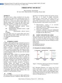
5 Optical Fiber Basics Recent advances in Fiber Optic technology have An optical Fiber is composed of three parts; the core, the significantly changed the telecommunications industry. The cladding, and the coating or buffer. The basic structure is ability to carry gigabits of information at the speed of light shown in Figure 1. The core is a cylindrical rod of dielectric increased the research potential in optical fibers. material and is generally made of glass. Light propagates Simultaneous improvements and cost reductions in mainly along the core of the Fiber [1]. optoelectronic components led to similar emergence of new product areas. Last revolution emerged as designers to combine the product outgrowths of Fiber Optic telecommunications with optoelectronic devices to create Fiber Optic Sensors . Soon it was discovered that, with material loss almost disappearing, and the sensitivity for IATS'09, Karab k University, Karab k, Turkey 1 Keynote Address Fidanboylu, K.
6 , and Efendio lu, H. S. Figure 1. Basic structure of an optical Fiber . The cladding layer is made of a dielectric material with an index of refraction. The index of refraction of the cladding material is less than that of the core material. The cladding is generally made of glass or plastic. The cladding executes such functions as decreasing loss of light from core into the surrounding air, decreasing scattering loss at the surface of the core, protecting the Fiber from absorbing the surface contaminants and adding mechanical strength [1]. The coating or buffer is a layer of material used to protect an optical Fiber from physical damage. The material used for a buffer is a type of plastic. The buffer is elastic in nature and prevents abrasions [1]. The light-guiding principle along the Fiber is based on the total internal reflection . The angle at which total internal reflection occurs is called the critical angle of incidence. At any angle of incidence, greater than the critical angle, light is totally reflected back into the glass medium (see Figure Figure 3.)
7 Different types of optical fibers. 2). The critical angle of incidence is determined by using Snell's Law. Optical Fiber is an example of electromagnetic 3. Fiber Optic sensor Principles surface waveguide [1]. The general structure of an optical Fiber sensor system is shown in Figure 4. It consists of an optical source (Laser, LED, Laser diode etc), optical Fiber , sensing or modulator element (which transduces the measurand to an optical signal), an optical detector and processing electronics (oscilloscope, optical spectrum analyzer etc). Measurand Optical Fiber Optical Fiber Source Transducer Detector Figure 2. Total internal reflection in an optical Fiber . Electronic Optical fibers are divided into two groups called single Processing mode and multimode. In classifying the index of refraction profile, we differentiate between step index and gradient index. Step index fibers have a constant index profile over Figure 4. Basic components of an optical Fiber sensor the whole cross section.
8 Gradient index fibers have a system. nonlinear, rotationally symmetric index profile, which falls off from the center of the Fiber outwards [14]. Figure 3 Fiber Optic Sensors can be classified under three shows the different types of fibers. categories: The sensing location, the operating principle, and the application. Based on the sensing location, a Fiber Optic sensor can be classified as extrinsic or intrinsic. In an extrinsic Fiber Optic sensor (see Figure 5), the Fiber is simply used to carry light to and from an external optical device where the sensing takes place. In this cases, the Fiber just acts as a means of getting the light to the sensing location. 2 Keynote Address Fidanboylu, K., and Efendio lu, H. S. The upper plate can move in response to pressure. When the bend radius of the Fiber exceeds the critical angle necessary to confine the light to the core area, light starts leaking into the cladding resulting in an intensity modulation [16].
9 Figure 5. Extrinsic and intrinsic types of Fiber Optic Sensors . On the other hand, in an intrinsic Fiber Optic sensor one or more of the physical properties of the Fiber undergo a change (see Figure 5). Perturbations act on the Fiber and the Fiber in turn changes some characteristic of the light inside the Fiber [9]. Figure 6. Intrinsic Fiber Optic sensor . Based on the operating principle or modulation and Another type of intensity based Fiber Optic sensor is the demodulation process, a Fiber Optic sensor can be evanescent wave sensor (see Figure 7) that utilizes the classified as an intensity, a phase, a frequency, or a light energy which leaks from the core into the cladding. polarization sensor . All these parameters may be subject These Sensors are widely used as chemical Sensors . The to change due to external perturbations. Thus, by detecting sensing is accomplished by stripping the cladding from a these parameters and Their changes, the external section of the Fiber and using a light source having a perturbations can be sensed [10].
10 Wavelength that can be absorbed by the chemical that is to be detected. The resulting change in light intensity is a Based on the application, a Fiber Optic sensor can be measure of the chemical concentration. Measurements classified as follows: can also be performed in a similar method by replacing the Physical Sensors : Used to measure physical properties cladding with a material such as an organic dye whose like temperature, stress, etc. optical properties can be changed by the chemical under Chemical Sensors : Used for pH measurement, gas investigation [17]. analysis, spectroscopic studies, etc. Bio-medical Sensors : Used in bio-medical Applications like measurement of blood flow, glucose content etc. 4. Fiber Optic sensor Types Intensity Based Fiber Optic Sensors Intensity-based Fiber Optic Sensors rely on signal undergoing some loss. They are made by using an apparatus to convert what is being measured into a force that bends the Fiber and causes attenuation of the signal.