Transcription of FIBER OPTIC SYSTEM TEST PROCEDURES
1 FIBER OPTIC SYSTEM TEST PROCEDURES Data Systems Performance Engineering LLC performs three tests in order to determine FIBER OPTIC cable adequacy. The order in which the tests are to be performed is not particularly critical. This document is not intended to be training material for optical testing . A. optical Power Loss Test. Many testing services rely on data from an optical Time Domain Reflectometer (OTDR) to determine optical power los through a FIBER OPTIC cable. OTDR measurements are calculations and are not as accurate as measurements made with the Double-Ended Loss Test shown immediately below. Equipment required: FIBER OPTIC Light source (850 nanometer or 1310 nanometer as required for multimode cables) FIBER OPTIC Power meter Two known good reference cables Two couplers In a double-ended loss test, the cable to be tested is connected between two reference cables, one attached to the source and one to the meter.
2 Using this test, the cumulative losses of two connectors is measured: one on each end, plus the loss of all the cable or cables in between. The cables need to be tested at the wavelength of the signal to be transmitted through the FIBER : 850 or 1310 nanometers. It is necessary to know the length of the cable to be tested before conducting the test. This may require measuring the cable length with an optical Time Domain Reflectometer. Step One: Clean the ends of the reference cables with an isopropyl alcohol soaked wipe. Step Two: Insert one test cable into the light source. Step Three: Insert the other test cable into the power meter Step Four: Connect the open ends of the cables together with a coupler. Step Five: Turn on the light source and the power meter.
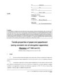
3 Measure the dB loss of the reference cable-coupler assembly. Record this number. Please see Figure 1 below. Figure 1 Step Six: Connect the cable to be tested (usually patch cable on one end to patch cable on the other end including all intermediate patch panels and premise wiring) between the ends of the reference cables using couplers. Record this dB loss. Subtract the measurement recorded from the reference cable from the total measurement. This will be the dB loss for the cable under test. Please see Figure 2 below. Figure 2 The loss measured should be less than the calculated loss. In order to obtain a calculated loss value, it is necessary to know the cable length and the manufacturer s specifications for cable loss per foot or per meter.
4 To obtain the calculated loss value, one multiplies the cable length by the loss per unit of measurement, then adds a factor in to account for connector and coupler losses. For example, a typical multimode micron cable has an insertion loss of dB per kilometer. Each multimode connector has an insertion loss of dB. Each coupler has an insertion loss of dB. Using these values, a 500 foot total length FIBER OPTIC cable with a patch cable at each end and two patch panels between the ends would have the following calculated loss: dB/kilometer X kilometer = dB for the cable. There are 6 connectors X dB per connector = dB There are two couplers X dB per coupler = dB So total calculated loss is + dB + dB = dB.
5 If the measured loss value was greater than the calculated loss value there is a cable or connector problem to be resolved. B. optical Time Domain Reflectometer Test FIBER OTDR s are useful for determination of overall cable quality. The OTDR can check for cable problems such as defective cables, splice problems, inadequate bend radius, FIBER cable microcracks, etc. The FIBER OPTIC TDR is especially useful to determine overall cable length. It should be noted, however, that it is necessary to have some idea of how long the cable actually is before trying to get cable length information from the OTDR. Anomalies shown at the cable end point on the OTDR display can be misleading and confusing. FIBER OPTIC TDR units can check for cable and splice attenuation, but these measurements are not as accurate as the power meter-light source measurement.
6 Step 1. Set the test parameters into the OTDR. Depending on the OTDR used, the test parameters may include the laser wavelength (1310 nanometers for this application), the distance range (in kilometers), the pulse width of the test pulse (depending on length of the FIBER to be measured), the acquisition time (the longer the acquisition time the better the image resolution), the index of refraction of the FIBER OPTIC cable, and the helix factor of the FIBER OPTIC cable (if available). Step 2. Connect the OTDR to one end of a launch cable (may also be called a dead band cable). Launch cables are necessary for most OTDR units because the OTDR is effectively blind for some distance from the light launch point. A launch cable is typically 200 meters in length.
7 Connect the other end of the launch cable to the FIBER to be tested (including all interim connections such as patch panels) (length of the dead band cable depends on the OTDR manufacturer). Turn on the OTDR and let it scan the FIBER under test. After the image has fully formed, examine it for abnormalities. The splices and junctions should be apparent but not excessive in attenuation. Individual splice losses may be measured using the four point loss method on the OTDR. Step 3. If there are anomalies found, it is necessary to determine if these anomalies are legitimate or reflections. Connect the OTDR and dead band cable to the other end of the cable under test and repeat the measurement. If the anomalies follow the launch point (for example, an anomaly on a 500 foot cable is 200 feet from the launch point at one end of the cable and 300 feet from the launch point at the opposite end of the cable) the problem is legitimate.
8 If the anomaly does not move it is most likely a reflection of some sort and can be disregarded. There may, of course be other types of anomalies discovered. To assure accurate test results, only experienced operators should use the OTDR. C. Connector Polishing Every connector in the SYSTEM (including those in patch panels) should be checked by using a 200X FIBER OPTIC microscope. This test should be done with both ends of the FIBER disconnected. Step 1. Clean the ends of the connectors with an isopropyl alcohol soaked wipe. Allow the connectors to dry. Step 2. Insert the connector end into the FIBER microscope. Turn on the light source. Step 3. Observe the end of the FIBER . The core should appear as a black dot. The cladding should appear lighter than the core.
9 The end of the connector should appear smooth. Scratches in the connector optical assembly, excess epoxy, or poor connector polishing will require remedial action. Replace cable or connectors determined to be defective. Figure 3 below shows a good FIBER OPTIC connector end and several examples of bad FIBER OPTIC connector ends. Figure 3