Transcription of Field Notching and Drilling of Laminated Veneer Lumber
1 TECHNICAL NOTE. Field Notching and Drilling of Laminated Veneer Lumber Number G535B. February 2020. Introduction Laminated Veneer Lumber (LVL) is an engineered wood product manufactured from specially selected veneers of varying strength and stiffness properties. LVL products are often specified where a certain span, strength and/or stiffness is required. As such, LVL products are generally designed for and used in applications where they will be highly stressed under design loads. For this reason, Field modifications, such as Notching , tapering or Drilling , not shown on the design or shop drawings, should be avoided and never done without a thorough understanding of the effects on the structural integrity of a member. Most LVL products are used as beams and headers loaded parallel to the gluelines. Any Drilling , tapering or Notching that takes place in LVL reduces the net section and may introduce stress concentrations at the Notching or Drilling location.
2 Therefore, it is easy to see why a cautious approach to Field modifications is vital. This Technical Note provides prescriptive recommendations for Field Notching , tapering and Drilling LVL beams. Notching Notching of LVL beams should be avoided whenever possible, especially on the tension side of a member. Tension-side Notching of LVL beams is not recommended except at end bearings and then only under specific conditions. The Notching of LVL beams on the tension side results in decreased strength caused by stress concentrations that develop around the notch and a reduction of the net cross section resisting the bending and shear forces. Such notches induce perpendicular-to-grain tensile stresses which, in conjunction with horizontal shear forces, can cause splitting along the grain, typically starting at the inside corner of the notch. Stress concentrations, due to notches, can be reduced by using a gradually tapered notch configuration in lieu of a square-cornered notch.
3 Rounding the square corner Form No. G535B 2020 APA The Engineered Wood Association 1. Field Notching and Drilling of Laminated Veneer Lumber of a notch with a radius of approximately 1/2 inch is also recommended to reduce stress concentrations in these areas. LVL beams illustrated in Figure 1 are assumed to be simple span subjected to uniform loads. All equations and Notching guidelines are presented using the same assumptions. If this information is applied to continuous or cantilevered beams, it should be used with extreme caution and only based on rational engineering analyses. Where LVL beams are notched at the ends for bearing over a support, the notch depth is recommended to not exceed 1/10 of the beam depth (Figure 1(e)). Within the limitation given above, the shear stress at the notch can be calculated in accordance with Figure 1(e). For notches on the compression side, a less severe condition exists and equations for the analysis of the effects of these notches are also given in Figure 1.
4 The equations given are empirical in nature and were developed for the conditions shown. As the Notching provisions given in this Technical Note are limited to uniformly loaded simple- span beams, the notches shown in Figure 1 occur in areas of high shear and lower moment. For this reason, the design equations given are shear equations. When necessary to cut a small notch in the top of an LVL beam (in the compression side) to provide passage for small-diameter pipe or conduit, the cut should be made in an area of the beam stressed to less than 50% of the allowable bending stress. The net section in this area should be checked for shear and bending stresses to ensure adequate performance. All Field notches should be accurately cut. It is important to understand that improperly cut Field notches may reduce the capacity of a beam and cause serious structural failure. Avoid over- cutting at the corners of the notch.
5 Drilling a pilot hole in a member at the interior corner of a notch as a stop point for the saw blade provides both a rounded corner and minimizes over- cutting at the corner. It should be recognized that the top of an LVL beam might not always be stressed in compression and the bottom of an LVL beam might not always be stressed in tension. For example, if the LVL beam is designed for wind uplift, the top of the LVL will be stressed in tension and the bottom of the LVL will be stressed in compression. In this case, the recommendations given above should be applied accordingly. Furthermore, when evaluating the effect of Notching , the shear force within a distance from supports equal to the beam depth should not be neglected, as typically permitted by the design of rectangular wood members in accordance with the National Design Specification for Wood Construction (NDS) in the and the Wood Design Manual in Canada.
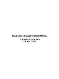
6 Form No. G535B 2020 APA The Engineered Wood Association 2. Field Notching and Drilling of Laminated Veneer Lumber FIGURE 1. SHEAR DESIGN EQUATIONS FOR NOTCHED AND TAPERED LVL BEAMS. Compression side Compression side d d 3V 3V. fv = fv =. 2bd 2bd (a) Square End Bearing (b) Slope End Bearing Maximum 1/3 Maximum of the span 1/3 of the span e e max. d d de de When e de, fv = 3V When e de, fv = 3V. 2b d . de (. d de e ) 2b d . d de de (e ). When e > de, fv = 3V When e > de, fv = 3V. 2bde 2bde (c) Sloped End Cut for Roof Drainage (d) Compression-side Notch de d max. ( ). 2. fv = 3V d 2bde de (e) Tension-side Notch fv = shear stress (psi) V = shear force at notch location (lb) b = width of beam (in.). d = depth of beam (in.) de = effective depth as shown (in.) e = length of notch as shown (in.). Form No. G535B 2020 APA The Engineered Wood Association 3. Field Notching and Drilling of Laminated Veneer Lumber Holes Horizontal Holes Like notches, holes in an LVL beam reduce the net section of the beam at the hole location and introduce stress concentrations.
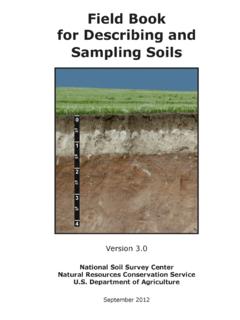
7 This causes a reduction in the beam capacity. For this reason, horizontal holes in LVL are limited in size and location to maintain the structural integrity of the beam. Figure 2 shows the zones of a uniformly loaded beam in simple or multiple spans, where the Field Drilling of holes may be considered. The requirements given consider the effect of the horizontal hole on the shear and moment capacities of an LVL beam, and may be applied to multiple-piece built-up LVL beams. APA Technical Note, Effect of Large Diameter Horizontal Holes on the Bending and Shear Properties of Laminated Veneer Lumber , Form V900, provides additional engineering guidelines where larger horizontal holes than those specified in this document cannot be avoided in design. FIGURE 2. PERMISSABLE HORIZONTAL ROUND HOLE LOCATIONS FOR LVL BEAMS UNDER UNIFORM LOADS. Uniform Load (plf). 1/3 d d 1/3 d 1/3 d Minimum horizontal spacing = 2 x diameter of the larger hole 1/3 span 1/3 span 1/3 span = Zones where horizontal holes are permitted for passage of wires, conduit, etc.
8 For beam depth of 3-1/2, 5-1/2, and 7-1/4 inches, the maximum hole diameter is 3/4, 1-1/8, and 1-1/2. inches, respectively. For deeper beams, the maximum hole diameter is 2 inches. The maximum number of holes for each span is limited to three. Holes should not be cut in cantilevers. Form No. G535B 2020 APA The Engineered Wood Association 4. Field Notching and Drilling of Laminated Veneer Lumber A 1-inch-diameter or smaller hole may be cut at the middle 1/3 of the beam depth anywhere along the span, except for the area that is within 6 inches of clear distance between the face of the support and the nearest edge of the hole (see Figure 3), provided the following conditions are all met: 1. the beam is at least 7-1/4 inches in depth , 2. the beam is subject to uniform loads only, 3. the span-to- depth ratio (l/d) is at least 11, 4. the maximum number of holes for each span is limited to three, 5.
9 The horizontal spacing must be a minimum of two diameters clear distance between adjacent holes based on the diameter of the larger hole, and 6. the hole must not be cut in cantilevers. FIGURE 3. ZONES WHERE 1-INCH OR SMALLER DIAMETER HORIZONTAL HOLES ARE PERMITTED IN A. UNIFORMLY L OADED BEAM (D 7-1/4 INCHES). Uniform Load (plf). 1/3 d 1/3 d 1/3 d . Minimum 2 x diameter of the larger hole l Zones where 1-inch or smaller diameter horizontal holes are permitted for passage of wires, conduit, etc. a) the maximum number of holes for each span shall not exceed three and b) the hole must not be cut in cantilevers. = 6 inches minimum when l/d 11, or l/6 minimum when l/d < 11. If l/d of the beam is less than 11, the 1-inch diameter or smaller hole may be cut in accordance with the provisions listed above Beam depth , Span when d (in.) l/d = 11. except that the location of the hole must maintain a clear distance 7-1/4 6'-8".
10 Between the face of the support and the nearest edge of the hole of 7-1/2 6'-11". at least 1/6 of the span. 9-1/4 8'-6". 9-1/2 8'-9". Field -drilled horizontal holes should be used for access only 11-1/4 10'-4". and should not be used as attachment points for brackets or 11-7/8 10'-11". other load bearing hardware unless specifically designed as 14 12'-10". such by an engineer or designer. Examples of access holes 16 14'-8". include those used for the passage of wires, electrical conduit, 18 16'-6". small-diameter sprinkler pipes, fiber-optic cables and other 20 18'-4". small, lightweight materials. For LVL beams that have been 22 20'-2". over-sized, the guidelines given above may be relaxed based 24 22'-0". Form No. G535B 2020 APA The Engineered Wood Association 5. Field Notching and Drilling of Laminated Veneer Lumber on an engineering analysis. When holes are required to be drilled outside the allowable zones, an engineering analysis should be conducted and approved by an engineer or architect qualified in wood design.