Transcription of FIELDVUE DLC3000 Series Digital Level Controllers
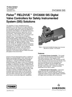
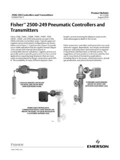
1 Product Bulletin : DLC3000 . December 2006 DLC3000 Digital Level Controllers FIELDVUER DLC3000 Series Digital Level Controllers FIELDVUER DLC3000 Series Digital Level Controllers The connection for HART communication may be (figure 1) are used with Level sensors to measure made at any point in the field wiring that meets the liquid Level , the Level of the interface between two HART impedance requirements. Configuration, liquids, or liquid specific gravity (density). Changes calibration, diagnostics, parameter review, signal in Level or specific gravity exert a buoyant force on a monitoring and alert monitoring are all available displacer, which rotates a torque tube shaft. The through the HART protocol. Information from the Digital Level controller converts this rotational motion field can be integrated into control systems or be to an electronic signal. received on a single loop basis. DLC3000 Series Digital Level Controllers are DLC3000 Series Digital Level Controllers are designed to directly replace standard pneumatic and communicating, microprocessor-based instruments electronic Level transmitters.
2 Type DLC3010 Digital that can be configured to sense the Level , interface Level Controllers mount on a wide variety of FisherR. Level , or density of liquids. In addition to the normal 249 Series cageless and caged Level sensors. function of providing a 4 to 20 milliampere current signal, DLC3000 Series Digital Level Controllers , Note using the HARTR communications protocol, give easy access to information critical to process Neither Emerson, Emerson Process operation. You can obtain information about the Management, nor any of their affiliated process, instrument, or sensor using the Model 375 entities assumes responsibility for the Field Communicator. Advanced user-interface selection, use, and maintenance of any capabilities are enabled by AMSt Suite: Intelligent product. Responsibility for the Device Manager. The DLC3000 Series can be used selection, use, and maintenance of any in analog or HART Digital signaling mode with the product remains with the purchaser Emerson Process Management DeltaVt system.
3 And end-user. W7977 / IL. Figure 1. FIELDVUER DLC3000 Series Digital Level controller D102727X012. Product Bulletin : DLC3000 . DLC3000 Digital Level Controllers December 2006. DLC3000 Series Digital Level controller Specifications Available Configurations Performance Type DLC3010 Digital Level controller : w/ 3-Inch DLC3000 w/ All Mounts on fisher 249 Series caged and cageless PERFORMANCE. Digital Level 249W, Using Other 249. sensors. See tables 4 and 5 and sensor CRITERIA. controller (1). a 14-inch Series Displacer description. Independent $ of $ of $ of Function: Transmitter Linearity output span output span output span Communications Protocol: HART < of Hysteresis . output span Input Signal(1) $ of full $ of $ of Repeatability scale output output span output span Level , Interface, or Density: Rotary motion of torque tube shaft proportional to changes in liquid < of Dead Band . input span Level , interface Level , or density that change the Hysteresis plus < of < of buoyancy of a displacer.
4 Deadband . output span output span Process Temperature: Interface for 2- or 3-wire NOTE: At full design span, reference conditions. 1. To lever assembly rotation inputs. 100 ohm platinum RTD for sensing process temperature, or optional user-entered target temperature to permit compensating for changes At effective proportional band (PB)<100%, in specific gravity linearity, dead band, and repeatability are derated by the factor (100%/PB). Output Signal(1). Operating Influences Analog: 4 to 20 milliamperes dc (J direct action increasing Level , interface, or density Power Supply Effect: Output changes < of increases output; or J reverse action increasing full scale when supply varies between min. and Level , interface, or density decreases output) max voltage specifications. Transient Voltage Protection: The loop High saturation: mA. Low saturation: mA terminals are protected by a transient voltage suppressor. The specifications are as follows: High alarm: mA. Low Alarm: mA Pulse Waveform Max VCL Max IPP.
5 Rise Time Decay to (Clamping (Pulse Peak Only one of the above high/low alarm definitions Voltage) (V) @ Current) (A). (ms) 50% (ms). is available in a given configuration. NAMUR NE. 10 1000 16. 43 compliant when high alarm Level is selected. 8 20 121 83. Digital : HART 1200 Baud FSK (frequency shift Note: s = microsecond keyed). HART impedance requirements must be met to Ambient Temperature: The combined enable communication. Total shunt impedance temperature effect on zero and span without the across the master device connections (excluding 249 sensor is less than of full scale per the master and transmitter impedance) must be degree Kelvin over the operating range 40 to between 230 and 1100 ohms. The transmitter 80_C ( 40 to 176_F). HART receive impedance is defined as: Process Temperature: The torque rate is Rx: 42K ohms and affected by the process temperature (see figure Cx: 14 nF 3). The process density may also be affected by Note that in point-to-point configuration, analog the process temperature.
6 And Digital signalling are available. The instrument Process Density: The sensitivity to error in may be queried digitally for information, or placed knowledge of process density is proportional to in Burst mode to regularly transmit unsolicited the differential density of the calibration. If the process information digitally. In multi-drop mode, differential specific gravity is , an error of the output current is fixed at 4 mA, and only Digital specific gravity units in knowledge of a process communication is available. fluid density represents 10% of span. continued . 2. Product Bulletin : DLC3000 . December 2006 DLC3000 Digital Level Controllers Specifications (continued). Electromagnetic Interference (EMI): Tested per troubleshooting variables , and IEC 61326-1 (Edition ). Complies with Basic trending capability for PV, TV and SV. European EMC Directive. Meets emission limits for class A equipment (industrial locations) and LCD Meter Indications class B equipment (domestic locations).
7 Meets LCD meter indicates analog output on a percent immunity requirements for industrial locations scale bar graph. The meter also can be (Table in the IEC specification document). configured to display: Immunity performance is shown in table 1. Process variable in engineering units only. Percent range only. Supply Requirements (See figure 5) Percent range alternating with process variable or Process variable, alternating with process 12 to 30 volts dc; instrument has reverse polarity temperature (and degrees of pilot shaft rotation). protection. Electrical Classification A minimum compliance voltage of is required to guarantee HART communication. Hazardous Area: Explosion proof, Intrinsic Safety, Compensation Dust-Ignition proof Explosion proof, Non-incendive, Transducer compensation: for ambient Dust-Ignition proof, Intrinsic Safety temperature. APPROVED. Density parameter compensation: for process ATEX Intrinsic Safety, Type n, Flameproof temperature (requires user-supplied tables).
8 Manual compensation: for torque tube rate at IECEx Intrinsic Safety, Type n target process temperature is possible. SAA Flameproof Digital Monitors Refer to tables 8, 9, 10, 11, and 12 for additional approval information. Linked to jumper-selected Hi (factory default) Electrical Housing: NEMA 4X, CSA Enclosure, or Lo analog alarm signal: and IP66. Torque tube position transducer: Drive monitor and signal reasonableness monitor Minimum Differential Specific Gravity User-configurable alarms: Hi-Hi and Lo-Lo Limit process alarms With a nominal degrees torque tube shaft rotation for a 0 to 100 percent change in liquid HART-readable only: Level (specific gravity=1), the Digital Level RTD signal reasonableness monitor: When RTD controller can be adjusted to provide full output for installed an input range of 5% of nominal input span. This Processor free-time monitor. equates to a minimum differential specific gravity Writes-remaining in Non Volatile Memory monitor. of with standard volume displacers.
9 User-configurable alarms: Hi and Lo limit process See 249 Series sensor specifications for standard alarms, Hi and Lo limit process temperature displacer volumes and standard wall torque alarms, and Hi and Lo limit electronics tubes. Standard volume for 249C and 249CP. temperature alarms Series is 980 cm3 (60 in3), most others have standard volume of 1640 cm3 (100 in3). Diagnostics Operating at 5% proportional band will degrade accuracy by a factor of 20. Using a thin wall Output loop current diagnostic. torque tube, or doubling the displacer volume will LCD meter diagnostic. each roughly double the effective proportional Spot specific gravity measurement in Level mode: band. When proportional band of the system used to update specific gravity parameter to drops below 50%, changing displacer or torque improve process measurement tube should be considered if high accuracy is a Digital signal-tracing capability: by review of requirement. continued . 3. Product Bulletin : DLC3000 .
10 DLC3000 Digital Level Controllers December 2006. Specifications (continued). Mounting Positions Yamatake and FoxboroR/Eckhardt displacers available. J Level Signature Series Test Digital Level Controllers can be mounted right- or (Performance Validation Report) available (EMA. left-of-displacer, as shown in figure 9. only) for instruments factory-mounted on 249. Instrument orientation is normally with the sensor . J Factory Calibration: available for coupling access door at the bottom, to provide instruments factory-mounted on 249 sensor , proper drainage of lever chamber and terminal when application, process temperature and compartment, and to limit gravitational effect on density(s) are supplied. J Device is compatible the lever assembly. If alternate drainage is with user-specified remote indicator. provided by user, and a small performance loss is acceptable, the instrument could be mounted in 90 degree rotational increments around the pilot shaft axis. The LCD meter may be rotated in 90 Operating Limits degree increments to accommodate this.