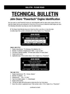
Transcription of Figure 1 On unloading augers that have not been updated to ...
1 (A) -Timing of two-piece unloading prevent damage to flighting, or excessive horsepower consump-tion when unloading , care must be taken to properly time the augerflighting between the front & rear properly time the flighting start with the front (gearbox) the auger until the trailing edge, ( nearest the bearing support) is at the 12 o'clock position, as viewed from the discharge install the outer auger with the leading edge at, or very near the 10 o'clock Position. ( See Figure 1. )On unloading augers that have not been updated to the floating hex shaft style system some modification may be required.(B) -Replacement of front auger. Additional items Hex shaft, (Qty 1.) Pin, (Qty 1.) Spacer, (Qty as required.) rear auger, measure approximately " behind the hex receiver hub and drill a 5/16" hole.( See Figure 2. ) pin 439-1548 and weld in and install auger. (Refer to paragraph (A) for clearance between the flighting and the carrier bearing support leg.)
2 Install spacer 1277949C1 between auger and bearing carrier to gain clearance if needed, but use as few as needed.(C) -Replacement of rear and install auger. (Refer to paragraph (A) for excessive clearance between auger end and spacer. ( See Figure 3. ) Also an auger with excessive clearance will appear to be to long when trying to install the end cap on the unloading required you can shorten the hex shaft on the front auger shaft by up to 7/8".BULLETIN - PLEASE READ! Figure 1 Figure 2TM0008)


