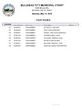
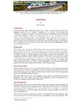
Transcription of Figure 1 Schematic of piping for a large AHU - Flow Control
1 Figure 1 Schematic of piping for a large AHU The question of how to Control water flow to an array of coils in a single air handling unit (AHU) was analyzed with PIPE-FLO ( Engineered Software, Olympia, WA, 1-800-786-8545). The base scenario consists of (6) 160 gpm coils selected for 15 ft of water pressure drop. The pipe sizing is based on a maximum of 10 feet per second max velocity. The Schematic shown omits the isolation valves that are typically installed to allow for maintenance issues at each coil. The results indicate that each coil will be within 1 ft of pressure drop for the Schematic shown, and that the resulting flow difference noticed should be less than +-5% of the design flow for each coil in the array.
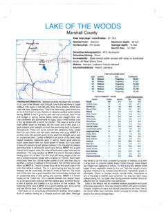
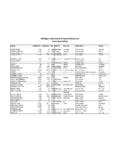
2 With a direct return piping layout as shown above, the difference in flow between all 6 coils were within 4% from design for the scenario shown. The impact of having a bullhead tee installed at the location of Coil-L1 was modeled to be equivalent to adding 9 elbows to that coil connection (ASHRAE F2009 page ). The result of having a bullhead tee on Coil-L1 results in less flow at design. As shown in Table 1, the part load variance from the mean flow to each coil increases as the total AHU flow decreases. Table 1. Summary of water flow rates through each coil Table 2.
3 Summary of pressure drops through each coil GPMD escription[gpm][gpm][gpm][gpm][gpm][gpm] [gpm][gpm][gpm][gpm][gpm][gpm]160 AHU [+%] [-%] 3 - 10 ft wpd coilCase 2 - 20 ft wpd coilCase 1 - Coil L1 bullhead teeBaseline - 15 ft wpd coilDescription[ft wpd][ft wpd][ft wpd][ft wpd][ft wpd][ft wpd][ft wpd][ft wpd][ft wpd][ft wpd][ft wpd][ft wpd]AHU Total [+%] [-%] - 15 ft wpd coilCase 1 - Coil L1 bullhead teeCase 2 - 20 ft wpd coilCase 3 - 10 ft wpd coil Figure 2 bullhead tee piping configuration Figure 3 Standard tee piping configurations