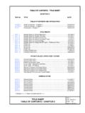
Transcription of FILE NO. TITLE DATE TABLE OF CONTENTS GENERAL …
1 TABLE OF CONTENTS PIER DETAILS. CHAPTER 15. FILE NO. TITLE DATE. TABLE OF CONTENTS . TABLE of CONTENTS Chapter 15 .. 27 Jul2017. TABLE of CONTENTS Chapter 15 .. 17 Aug2016. GENERAL guidelines AND TYPE SELECTION. GENERAL GENERAL GENERAL Virginia Pier Cap ..18 May2016. Virginia Pier Cap (Special Circumstances) ..18 May2016. Type Geotechnical Design Data 27 Jul2017. Architectural Treatment for Piers ..18 May2016. PIER COMPONENTS AND MISCELLANEOUS DETAILS. Double Overpass Clearance/Long Chord Layout ..18 May2016. Cap Length Criteria .. 27 Jul2017. Sample Anchor Bolt Layouts .. 27 Jul2017. Bottom Cap Slope and Cap Reinforcement ..18 May2016. Cap Reinforcement ..18 May2016. Seat Columns ..18 May2016. Columns ..18 May2016. Column Ties ..18 May2016. Footing Types and Details ..18 May2016. Pile Types ..18 May2016. Pile Types ..18 May2016. Pile and Drilled Shaft Requirements.
2 18 May2016. Drilled Shafts ..18 May2016. Drilled Shafts ..18 May2016. Drilled Shafts ..18 May2016. SAMPLE SHEETS AND DETAILING CHECK LIST. * Sample Multi-Column Pier Sheet .. 27 Jul2017. * Sample Hammerhead Pier Sheet ..18 May2016. * Sample Wall Pier Sheet ..18 May2016. * Sample Pile Bent Sheet ..18 May2016. Check 27 Jul2017. Check 27 Jul2017. * Indicates 11 x 17 sheet; all others are 8 x 11. PART 2. PIER DETAILS DATE: 27 Jul2017. TABLE OF CONTENTS CHAPTER 15 SHEET 1 of 2. FILE NO. TABLE OF CONTENTS PIER DETAILS. CHAPTER 15. FILE NO. TITLE DATE. SUPERSTRUCTURE FORCES. GENERAL 17 Dec2010. GENERAL GENERAL 17 Dec2010. Example 1: Varying Height/Stiffness ..11 Jan2011. Example 1: Varying Height/Stiffness ..11 Jan2011. Example 1: Varying Height/Stiffness ..11 Jan2011. Example 2: Unsymmetric Spans .. 17 Dec2010. Example 2: Unsymmetric Spans ..11 Jan2011. Example 3: Pile Bent.
3 17 Dec2010. Example 3: Pile Bent ..11 Jan2011. Example 3: Pile Bent ..11 Jan2011. Example 3: Pile Bent ..11 Jan2011. DESIGN / DETAILING FOR COLLISION FORCE. GENERAL 17 Dec2010. Multi-Column / Wall Piers Adjacent to Railway .. 17 Dec2010. Multi-Column / Wall Piers Adjacent to Railway .. 17 Dec2010. Hammerhead Piers Adjacent to 17 Dec2010. Hammerhead Piers Adjacent to 17 Dec2010. PIER PROTECTION SYSTEM. GENERAL GENERAL GENERAL Length of Pier Protection ..18 May2016. Length of Pier Protection ..18 May2016. Length of Pier Protection ..18 May2016. Length of Pier Protection ..18 May2016. Barrier Layout Example 1 ..18 May2016. Barrier Layout Example 2 ..18 May2016. Barrier Layout Example 2 ..18 May2016. Barrier Layout Example 3 ..18 May2016. Barrier Layout Example 3 ..18 May2016. Barrier Layout Example 3 ..18 May2016. Barrier Layout Example 4 ..18 May2016.
4 Barrier Layout Example 4 ..18 May2016. Barrier Layout Example 4 ..18 May2016. Barrier Layout Example 5 ..18 May2016. Barrier Layout Example 5 ..18 May2016. Barrier Layout Example 5 .. 17 Aug2016. * Indicates 11 x 17 sheet; all others are 8 x 11. PART 2. PIER DETAILS DATE: 17 Aug2016. TABLE OF CONTENTS CHAPTER 15 SHEET 2 of 2. FILE NO. INTRODUCTION. Piers transmit loads from the superstructure to the foundation. The intent of this chapter is to establish the practices and specific requirements of the Structure and Bridge Division for the design and detailing of piers and pile bents. It is expected that users of this chapter will adhere to the practices and requirements stated herein. A design waiver will be required for areas that are indicated as minimum standards or where the term shall is indicated. The designer shall be responsible for investigation, analysis and calculations necessary to secure a waiver from the State Structure and Bridge Engineer.
5 The designer must indicate in the waiver why the standard cannot be met. References to AASHTO LRFD specifications refer to the current AASHTO LRFD Bridge Design Specifications, current Interims and VDOT Modifications (current IIM-S&B-80). References to AASHTO standard bridge specifications refer to the AASHTO Standard Specifications for th Highway Bridges, 16 Edition, 1996, including the 1997 and 1998 Interims and VDOT. Modifications. Several major changes to past practices are as follows: 1. Added Virginia Pier Cap content. 2. Minimum vertical reinforcement criteria added for wall/solid piers. 3. Pier protection system limits revised. NOTE: Due to various restrictions on placing files in this manual onto the Internet, portions of the drawings shown do not necessarily reflect the correct line weights, line types, fonts, arrowheads, etc. Wherever discrepancies occur, the written text shall take precedence over any of the drawn views.
6 PART 2. PIER DETAILS DATE: 18 May2016. INTRODUCTION CHAPTER 15 SHEET 1 of 1. FILE NO. GENERAL INFORMATION: Specific types of piers and details are more cost effective or necessary due to aspects of the particular bridge grade and location. In GENERAL , it is beneficial to keep cap size, column size and pile type and size the same for all piers/bents on a project and/or corridor to enable the reuse of forms and to avoid ordering small quantities. On larger projects, additional column sizes or pile types may be warranted where heights, depths or design loads vary substantially across the spans. Drainage: See File No. for criteria on downspout / collector pipe placement. Multi-Column Piers: Multi-column piers are typically used where column heights are below 30 feet. Column spacing between 15 and 20 feet is generally cost effective. Cap ends shall not be rounded, but should be tapered for aesthetic purposes.
7 Concrete Class A3 (f'c =. 3,000 psi) should be used. Class A4 (f'c = 4,000 psi) may be used where warranted. The use of multi-column piers in areas where floating debris may lodge between columns should be avoided. On wide structures with more than five columns and/or cap lengths greater than 80 feet, designers should consider whether to split a multi-column pier into two piers especially where columns are short and contraction/expansion of the pier cap results in large internal forces. For piers with more than six columns and/or cap lengths greater than 100 feet, two piers are required. Hammerhead Piers: Hammerhead piers are typically used where column lengths on multi-column piers will require larger column sizes due to slenderness. Hammerhead piers are also an option where stream flow could result in debris build-up between columns of a multi- column pier.
8 Where stream flow is present, hammerhead piers shall be oriented parallel to the direction of flow. Small skews to the direction of flow are acceptable (0 to 5 degrees) where superstructure skew can be eliminated completely or reduced for specific design purposes. Specific design purposes include reducing skew to 10 degrees so V-load method can be used to determine cross frame forces on steel superstructure and reducing skew to 20 degrees so finite element analysis is not required. Small skews parallel to the direction of flow require concurrence of the hydraulic engineer. Wall/Solid Piers: Wall piers are typically used where multi-column piers may be used, but stream flow will result in debris build-up between columns. Wall piers may be more cost effective than multi-column piers when collision force is taken into account. Wall/Solid Piers continued on next sheet PIER DETAILS PART 2.
9 DATE: 18 May2016. GENERAL guidelines AND TYPE SELECTION SHEET 1 of 8. GENERAL guidelines FILE NO. GENERAL INFORMATION (continued): Wall/Solid Piers (continued): Concrete Class A3 (f'c = 3,000 psi) shall be used. Sloped (tapered/battered) walls shall not be used. Non-reinforced walls are prohibited. Wall piers shall be oriented parallel to the direction of flow. Caps are required where the width of wall is not sufficient for bearing layout (typically where two bearing lines are present). Cap Sloped Walls Cap Required Not Required (not to be used) for Bearing Layout for Bearing Layout Pile Bents: Pile bents are typically used over wetlands and/or bodies of water where driven square or cylinder prestressed concrete piles can reduce the environmental impact and pile or spread footings may not be feasible. Plumb piles are preferred. The outside pile on both sides of the bent may be battered to improve resistance to movement due to transverse forces only where future widening is not a concern.
10 Likewise, piles may be battered longitudinally at a fixed bent or bents to better fix the thermal center of a unit and handle longitudinal forces. Batter on piles should not exceed 1 : 6. Driving difficulties increase with the length of the pile. Before battering piles, designers should consider whether fixing more bents can adequately handle design loads and movement. Pile bents are often used in scourable areas. Designers should investigate both the existing ground and scoured condition as the assumed point of fixity for the piles can vary substantially. Additionally, pile driveability must be evaluated. The designers must determine if a pile can be driven deep enough (without overstressing the pile) so that it is stable after the scour occurs. Shorter design lengths will attract more load while longer lengths will increase slenderness. Assuming the number of piles equals the number of beam/girder lines is a good starting point for preliminary design.
