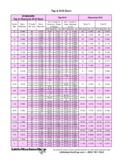
Transcription of Finite Element Analysis Using ABAQUS - University of Florida
1 Finite Element Analysis Using ABAQUS . EGM 6352 (Spring 2017). Instructor: Nam-Ho Kim Web: 1. methods of Analysis in ABAQUS . Interactive mode Create Analysis model and procedure Using GUI. Advantage: No need to remember commands Disadvantage: No automatic procedure for changing model or parameters Python script All GUI user actions will be saved as Python script Advantage: User can repeat the same command procedure Disadvantage: Need to learn Python language Analysis input file At the end, ABAQUS generates Analysis input file (text file). ABAQUS solver reads Analysis input file It is possible to manually create Analysis input file 2. Components in ABAQUS Model Creating nodes and elements (discretized geometry). Element section properties (area, moment of inertia, etc). Material data (linear/nonlinear, elastic/plastic, isotropic/orthotropic, etc). Loads and boundary conditions (nodal force, pressure, gravity, fixed displacement, joint, relation, etc). Analysis type (linear/nonlinear, static/dynamic, etc).
2 Output requests 3. Example: Overhead Hoist 4. Input File: *HEADING. Two-dimensional overhead hoist frame **. SI units (kg, m, s, N) ** History data 1-axis horizontal, 2-axis vertical **. *PREPRINT, ECHO=YES, MODEL=YES, HISTORY=YES * step , PERTURBATION. ** 10kN central load ** Model definition *STATIC. ** *BOUNDARY. *NODE, NSET=NALL 101, ENCASTRE. 101, 0., 0., 0. 103, 2. 102, 1., 0., 0. *CLOAD. 103, 2., 0., 0. 102, 2, 104, , , 0. *NODE PRINT. 105, , , 0. U, * Element , TYPE=T2D2, ELSET=FRAME RF, 11, 101, 102 *EL PRINT. 12, 102, 103 S, 13, 101, 104 **. 14, 102, 104 ** OUTPUT FOR ABAQUS QA PURPOSES. 15, 102, 105 **. 16, 103, 105 *EL FILE. 17, 104, 105 S, *SOLID SECTION, ELSET=FRAME, MATERIAL=STEEL *NODE FILE. ** diameter = 5mm --> area = m^2 U, RF. , *END step . *MATERIAL, NAME=STEEL. *ELASTIC. , 5. Format of Input File Model data section Information required to define the structure being analyzed History data section Type of simulation (static, dynamics, etc). The sequence of loading or events for which the response of the structure is required Divided into a sequence of steps Output request Input file Composed of a number of option blocks (describing a part of the model).
3 Each option block begins with a keyword line (starting with *), which is usually followed by one or more data lines. 6. Format of Input File cont. Keyword line * Element , TYPE = T2D2, ELSET = FRAME. Element set FRAME is 2-dimensional truss Element *NODE, NSET=PART1. All nodes below belong to a set PART1. * Element , TYPE = T2D2, ELSET = FRAME. Maximum 256 characters per line Data line - Keyword line usually followed by data lines *NODE. 101, 0., 0., 0. 102, 1., 0., 0. 103, 2., 0., 0. 104, , , 0. 105, , , 0. 7. Format of Input File cont. Model data Heading The first option in any ABAQUS input file must be *HEADING. Description of the problem *HEADING. Two-dimensional overhead hoist frame SI units (kg, m, s, N). 1-axis horizontal, 2-axis vertical Data file printing options Input file echo *PREPRINT, ECHO=YES, MODEL=YES, HISTORY=YES. Comments **. ** Model definition **. 8. Format of Input File cont. Element connectivity Keyword * Element specifies Element type, Element set * Element , TYPE=T2D2, ELSET=FRAME.
4 11, 101, 102. 12, 102, 103. 13, 101, 104. 14, 102, 104. 15, 102, 105. 16, 103, 105. 17, 104, 105. Section properties Keyword *SOLID SECTION specifies area, I, etc *SOLID SECTION, ELSET=FRAME, MATERIAL=STEEL. ** diameter = 5mm --> area = m^2. , 9. Format of Input File cont. Material properties Keyword *MATERIAL followed by various suboptions *MATERIAL, NAME=STEEL. *ELASTIC. , History data Starts with keyword * step , followed by the title of the step * step , PERTURBATION. 10kN central load Analysis procedure Use *STATIC immediately after * step . Boundary conditions Keyword *BOUNDARY. (UX, UY, UZ, UR1, UR2, URS) = (1, 2, 3, 4, 5, 6). 10. Format of Input File cont. Boundary conditions cont. Format: Node number, first dof, last dof, displ value 103, 2,2, 103, 2,2. 103, 2. 101, 1. 101, 2. Built in constraints ENCASTRE: Constraint on all displacements and rotations at a node PINNED: Constraint on all translational degrees of freedom XSYMM: Symmetry constraint about a plane of constant YSYMM: Symmetry constraint about a plane of constant ZSYMM: Symmetry constraint about a plane of constant XASYMM: Antisymmetry constraint about a plane of constant YASYMM: Antisymmetry constraint about a plane of constant ZASYMM: Antisymmetry constraint about a plane of constant 11.
5 Format of Input File cont. Applied loads concentrated loads, pressure loads, distributed traction loads, distributed edge loads and moment on shells, nonzero boundary conditions, body loads, and temperature *CLOAD. 102, 2, Output request neutral binary file (.odb), printed text file (.dat), restart file (.res), binary result file (.fil). *NODE PRINT. U, RF, *EL PRINT. S, End of step *END step . 12. Run ABAQUS . Data check ABAQUS job=frame datacheck interactive Show file Check for **ERROR ot **WARNING. Solving the problem ABAQUS job=frame continue interactive Show file 13. Postprocessing Graphical postprocessing ABAQUS viewer open Show labels Using Options> Common> Labels Plot> Deformed shape Change deformation scale factor Using Options> Common> Basic 14. NONLINEAR Analysis . Using ABAQUS . 15. Nonlinear Analysis Using ABAQUS . Geometric nonlinear (St. Venant-Kirchhoff material). * step , NLGEOM=YES, INC=150. Large deformation on, maximum No. of increments = 150. Time control *STATIC.
6 , , , initial time increment, final time, min increment, max increment 16. Tutorial: Bending of Cantilevered Beam Create a part Parts Name: Beam 2D Planar Deformable Shell . Approximate size = 20. Create lines: Rectangle (0,0) (10, ) Done Materials Name:Material-1 Mechanical Elasticity Elastic Young's modulus = 1E8 Poisson's ratio = 0 OK. Sections Name: Section-1 Solid Homogeneous Continue Material-1 Plane stress/strain thickness = OK. Parts Beam Section Assignments Select Beam Done . Section: Section-1 OK. 17. Tutorial: Bending of Cantilevered Beam Mesh control (Parts Beam Mesh (Empty). Menu Mesh Element Type Select Beam Done Family: Plane Strain, Check Incompatible modes OK. Menu Seed Edge Select top and bottom lines Done . Method: By number Number of elements = 40 OK. Menu Mesh Part Yes Assembly and Steps Assembly Instance Beam OK. Steps Name: Linear Procedure type: Linear perturbation . Continue OK. Constraints Cancel RP (0, ). Constraint Coupling Continue Select RP-1 Done.)
7 Surface Select left line of the beam Done Coupling type: continuous distributing OK. 18. Tutorial: Bending of Cantilevered Beam Load and BC. BCs step : Initial Displacement/Rotation Select tie right edge of the Beam Done Click U1 & U2 OK. Loads step : step -1 Moment Continue Select RP-1 . Done CM3: OK. Create job and solve the model Jobs Continue OK. Right click on Job-1 Submit OK. Postprocessing Right click on Job-1 Results Common options Deformation scale factor Uniform Value: 1. OK. Plot deformed shape 19. Tutorial: Bending of Cantilevered Beam Deformed shape from linear perturbation Analysis (Scale factor = ). 20. Tutorial: Bending of Cantilevered Beam Nonlinear simulation Go back to Model Delete step -1 (linear perturbation). Create a nonlinear step and submit the job Steps Procedure type: general Static, general Continue Nlgeom: on Incrementation: Max No of increments: 200 Initial: . Maximum: OK. Loads step : step -1 Moment Continue Select RP-1 . Done CM3: OK. Submit job OK.
8 21. Tutorial: Bending of Cantilevered Beam Deformed shape from nonlinear static Analysis (Scale factor = ). 22.