Transcription of Fire Alarm Panels - Advanced
1 Fire Alarm Panels User Manual The operation and functions described in this manual are available from Software Version 5000-050-04 onwards. 2 This page is intentionally blank 3 Table of Contents Page 1 5 STANDARDS .. 5 CAUTIONS AND WARNINGS .. 6 DESCRIPTION .. 6 5000 Series .. 6 5000V 6 5000N Series .. 6 2 CONTROLS AND 7 GRAPHICAL DISPLAY .. 7 LED STATUS INDICATORS .. 8 ZONE LED STATUS INDICATORS .. 8 CONTROL BUTTONS .. 9 NAVIGATION BUTTONS.
2 9 NUMBER AND LETTER BUTTONS .. 10 BUZZER .. 10 3 OPERATION .. 10 ACCESS LEVELS .. 10 Changing from Access Level 1 to Level 2 .. 11 Menu Access .. 11 Control Buttons at Level 1 .. 11 Changing from Access Level 2 to 1 .. 11 FIRE Alarm CONDITION .. 12 Detailed Fire Alarm Information .. 13 Investigation Delays .. 13 FAULT CONDITION .. 14 DISABLEMENT CONDITION .. 15 Disabled Inputs .. 15 Disabled Outputs .. 16 Alarm CONDITION .. 16 SUPERVISORY CONDITION .. 17 MULTIPLE CONDITIONS.
3 17 MENU FUNCTIONS .. 17 Using the Buttons to Navigate Menus .. 19 Selecting Menu Options .. 19 Selecting Individual Zone Numbers .. 19 VIEWING .. 20 View - Fires .. 20 View - Faults .. 20 View - Alarms .. 20 View - Disabled .. 20 View - Inputs .. 21 View - Outputs .. 21 View - Panel .. 22 Software .. 22 Local Hardware .. 23 Network Hardware .. 24 View - Log .. 24 Event Log .. 24 Alarm Counter .. 25 View - Network .. 25 View - 25 View - Supervisory .. 25 DISABLING.
4 26 Disable - Zones and Inputs .. 26 Disable - Outputs .. 27 All Sounder Outputs .. 27 All Beacon Outputs .. 27 Fire Routing Outputs .. 27 4 Fire Protection Outputs .. 27 Fault Routing 28 All Other Relay Outputs .. 28 Selected Outputs .. 28 Pager .. 28 Only Selected Outputs .. 28 Disable - Controls .. 28 Disable User ID .. 29 Disable Groups .. 29 ENABLING .. 30 Enable - Zones and Inputs .. 30 Enable - Outputs .. 30 Enable - Groups .. 30 Enable - Remote .. 30 DELAYS.
5 31 Turn Off Delay Mode .. 31 Turn On Delay-Mode .. 31 Extend Delays .. 32 Holiday / Inhibit .. 32 TESTING .. 33 Test - Zones .. 33 Test - Display .. 34 Test - Buzzer .. 34 Test - Printer .. 35 Test - Outputs .. 35 TOOLS .. 36 Printing .. 36 Printer Communications Settings .. 36 Set-up Printer .. 36 Print Inputs .. 37 Print Outputs .. 37 Print Faults .. 37 Print Disabled .. 38 Print - Log .. 38 Print - Feed Paper .. 38 Change-Time .. 39 5 1 Introduction Standards Advanced Electronics Ltd declares that the products identified below conform to the essential requirements specified in the Construction Products Directive 89/106/EEC: 0786-CPD-20952 EN54-2: 1997 +A1:2006 Control and indicating equipment for fire detection and fire Alarm systems for buildings Provided options.
6 - Outputs to Fire Alarm Devices - Output to Fire Routing Equipment - Output to Fire Protection Equipment - Output to Fault Routing Equipment - Investigation Delays to Outputs - Dependency on more than one Alarm signal - Fault Signals from Points - Disablement of Points - Alarm Counter - Test Condition - Standardised Input / Output EN54-4: 1997 +A1:2002 +A2:2006 Power supply equipment for fire detection and fire Alarm systems for buildings Mx-5100, Mx-5200, Mx-5400, MX-5800 Mx-5100V, Mx-5200V, Mx-5400V, MX-5800V Mx-5100N, Mx-5200N, Mx-5400N, MX-5800N In addition, the products comply with the following: Low Voltage Directive 2006/95/EC BS EN60950-1: 2006 Safety of information technology equipment Electromagnetic Compatibility Directive 2004/108/EC BS EN55022: 1998 Emissions, Class B BS EN50130-4: 1996 +A2.
7 2003 Immunity, Product Family Standard 6 Cautions and Warnings STOP BEFORE INSTALLATION Refer To the Ratings shown on the label inside the product and to the Specifications Chart in this document. Please read this manual carefully. If you are unclear on any point DO NOT proceed. Contact the manufacturer or supplier for clarification and guidance. Only Trained service personnel should undertake the Installation, Programming and Maintenance of this equipment. This product has been designed to comply with the requirements of the Low Voltage Safety and the EMC Directives.
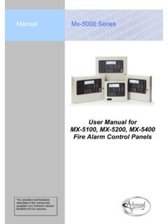
8 Failure to follow the installation instructions may compromise its adherence to these standards. ATTENTION OBSERVE PRECAUTIONS FOR HANDLING ELECTROSTATIC SENSITIVE DEVICES This equipment is constructed with static sensitive components. Observe anti-static precautions at all times when handling printed circuit boards. Wear an anti-static earth strap connected to panel enclosure earth point. Before installing or removing any printed circuit boards remove all sources of power (mains and battery). Description This manual covers the use and operation of the 5000, 5000V & 5000N Series Fire Alarm Control Panels .
9 Refer to the Installation and Commissioning Manual (Document No. 680-165) for details of how to install and program the panel. All panel models are available in a range of enclosure sizes and with a range of alternative optional features. 5000 Series The 5100 is a Single Loop, analogue addressable Fire Alarm Control Panel. The 5200 is a Two Loop, analogue addressable Fire Alarm Control Panel. The 5400 is a Multiple Loop, analogue addressable Fire Alarm Control Panel with provision for up to four loops.
10 All above models are designed for use with the Apollo (Discovery, Explorer, XP95 and Series 90) and Hochiki (ESP) fire detection devices. 5000V Series The 5100V is a Single Loop, analogue addressable Fire Alarm Control Panel. The 5200V is a Two Loop, analogue addressable Fire Alarm Control Panel. The 5400V is a Multiple Loop, analogue addressable Fire Alarm Control Panel with provision for up to four loops. All above models are designed for use with the Advanced (AV) fire detection devices. 5000N Series The 5100N is a Single Loop, analogue addressable Fire Alarm Control Panel.