Transcription of First Law of Thermodynamics Control Volumes
1 M. Bahrami ENSC 388 (F09) 1st Law of Thermodynamics : Control Volumes 1 The First Law of Thermodynamics : Control Volumes Here we will extend the conservation of energy to systems that involve mass flow across their boundaries, Control Volumes . Any arbitrary region in space can be selected as Control volume. There are no concrete rules for the selection of Control Volumes . The boundary of Control volume is called a Control surface. Conservation of Mass Like energy, mass is a conserved property, and it cannot be created or destroyed.
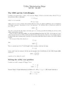
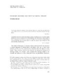
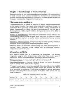
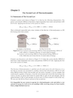
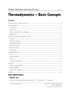
2 Mass and energy can be converted to each other according to Einstein s formula: E = mc2, where c is the speed of light. However, except for nuclear reactions, the conservation of mass principle holds for all processes. For a Control volume undergoing a process, the conservation of mass can be stated as: total mass entering CV total mass leaving CV = net change in mass within CV CVeimmm Fig. 1: Conservation of mass principle for a CV. The conservation of mass can also be expressed in the rate form: dtdmmmCVei/ The amount of mass flowing through a cross section per unit time is called the mass flow rate and is denoted by m.
3 The mass flow rate through a differential area dA is: dm = Vn dA where Vn is the velocity component normal to dA. Thus, the mass flow rate for the entire cross section is obtained by: m i m o Control volume M. Bahrami ENSC 388 (F09) 1st Law of Thermodynamics : Control Volumes 2 )kg/s(dAVmAn Assuming one dimensional flow, a uniform (averaged or bulk) velocity can be defined: m = V A (kg/s) where V (m/s) is the fluid velocity normal to the cross sectional area. The volume of the fluid flowing through a cross section per unit time is called the volumetric flow, V : /s)(m3 VAdAVVAn The mass and volume flow rate are related by: m = V = V / v.
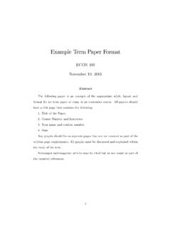
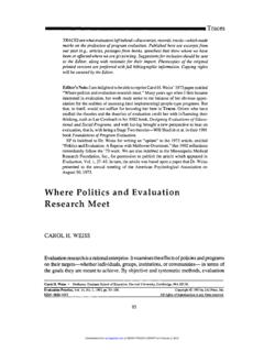
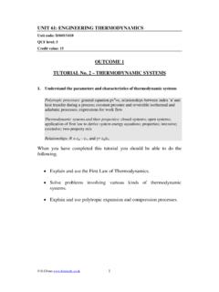
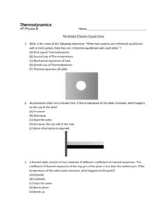
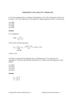
4 Conservation of Energy For Control Volumes , an additional mechanism can change the energy of a system: mass flow in and out of the Control volume. Therefore, the conservation of energy for a Control volume undergoing a process can be expressed as total energy crossing boundary as heat and work + total energy of mass entering CV total energy of mass leaving CV = net change in energy of CV CVmassoutmassinEEEWQ ,, This equation is applicable to any Control volume undergoing any process. This equation can also be expressed in rate form: dtdEdtdEdtdEWQCV massoutmassin///,, Fig.
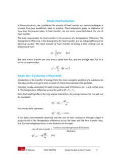
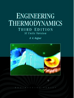
5 2: Energy content of CV can be changed by mass flow in/out and heat and work interactions. Work flow: is the energy that is required to push fluid into or out of a Control volume. Consider an imaginary piston (that pushes the fluid to CV) where the fluid pressure is P and the cross sectional area is A. The force acting on the piston is F = PA. Mass in Mass out Q W Control volume M. Bahrami ENSC 388 (F09) 1st Law of Thermodynamics : Control Volumes 3 Fig. 3: schematic for flow work. The work done in pushing the fluid is: Wflow = = = PV (kJ) or in a unit basis, wflow = Wflow / m = Pv (kJ/kg) Note that the flow work is expressed in terms of properties.
6 The flow work can also be written as a rate equation. The fluid entering or leaving a Control volume possesses an additional form of energy (flow energy Pv). Therefore, the total energy of a flowing fluid on a unit mass basis (denoted by ) becomes: = Pv + e = Pv + (u + ke + pe) (kJ/kg) Recall that enthalpy is defined as: h = u + Pv. Therefore, the above equation becomes: = h + ke + pe = h + V2 / 2 + gz (kJ/kg) The property is called methalpy. By using enthalpy instead of internal energy, the energy associated with flow work into/out of Control volume is automatically taken care of.
7 This is the main reason that enthalpy is defined! Steady State Flow Process A process during which a fluid flows through a Control volume steadily is called steady state process. A large number of devices such as turbines, compressors, and nozzles operates under the same conditions for a long time and can be modeled (classified) as steady flow devices. The term steady implies no change with time. The term uniform implies no change with location over a specified region. A steady flow is characterized by the following: s A PFlow direction P M. Bahrami ENSC 388 (F09) 1st Law of Thermodynamics : Control Volumes 4 1 No properties within the CV change with time.
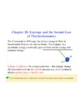
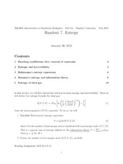
8 Thus, volume, mass, and energy of CV remains constant. As a result, the boundary work is zero. Also, total mass entering the CV must be equal to total mass leaving CV. 2 No properties change at the boundary of the CV with time. It means that the mass flow rate and the properties of the fluid at an opening must remain constant during a steady flow. 3 The heat and mass interactions between the CV and its surroundings do not change with time. Using the above observation, the conservation of energy principle for a general steady flow system with multiple inlets and exits can be written as: iieeiiiieeeemmWQgzVhmgzVhmWQ 2222 Nozzles and Diffusers A nozzle is a device that increases the velocity of a fluid at the expense of pressure.
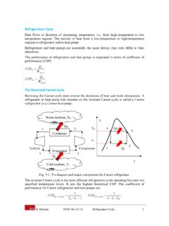
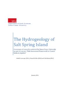
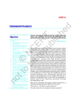
9 A diffuser is a device that increases the pressure of a fluid by slowing it down. The cross sectional area of a nozzle decreases in the flow direction for subsonic flows and increase for supersonic flows. Fig. 4: Schematic of nozzle. For a nozzle, common assumptions and idealizations are: Q = 0, no time for heat transfer, due to high velocity W = 0, nozzles include no shaft or electric resistance wires PE = 0, no change in fluid elevation. Mass equation for nozzles becomes: m 1 = m 2 or 1A1V1 = 2A2V2 Nozzle1 2A1 > A2 V2 > V1 P1 < P2 Control Volume Q = 0W = 0 M.
10 Bahrami ENSC 388 (F09) 1st Law of Thermodynamics : Control Volumes 5 Energy balance: Q W = m 1 1 m 2 2 (h + V2 / 2)at inlet = (h + V2 / 2)at exit Diffusers are exactly the same device as nozzles; the only difference is the direction of the flow. Thus, all equations derived for nozzles hold for diffusers. Fig. 5: Schematic for diffuser. Example 1: Nozzle Steam enters a converging diverging nozzle operating at steady state with P1 = MPa, T1 = 400 C and a velocity of 10 m/s. The steam flows through the nozzle with negligible heat transfer and no significant change in potential energy.