Transcription of Fisher 2052 Diaphragm Rotary Actuator - Emerson
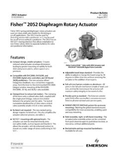
1 2052 Diaphragm Rotary of Diaphragm Plate, Diaphragm Rod Assembly, and Spring(s) Or Replacing Actuator Mounting (3610, DVC6020, or DVC6200) Mounted 1. Fisher Control Disk Valve with 2052 actuator and DVC6200 Digital Valve ControllerW9418-2 IntroductionScope of ManualThis instruction manual includes installation, adjustment, operation, maintenance, and parts information for theFisher 2052 Diaphragm Rotary Actuator (figure 1). Instructions for the control valve, positioner, manual Actuator , andother accessories are included in separate not install, operate, or maintain a 2052 actuator without being fully trained and qualified in valve, Actuator , andaccessory installation, operation, and maintenance.
2 To avoid personal injury or property damage, it is important tocarefully read, understand, and follow all the contents of this manual, including all safety cautions and warnings. If youhave any questions about these instructions, contact your Emerson sales office or Local Business Partner spring and Diaphragm Rotary actuators are used on Rotary shaft valve bodies for throttling or on off 2052 may be used for on off service without a positioner, or it may be used for throttling service with a positioner,depending on service conditions. The 2052 has an ISO 5211 mating interface that allows installation to non Fishervalves.
3 Refer to separate bulletins for valve and positioner top-mounted handwheel option is available for infrequent service as a manual Actuator . For repeated or daily manualoperation, the unit should be equipped with a side-mounted declutchable 1078 manual Actuator . Externally adjustabletravel stops are used to limit the degree of rotation at both ends of the Actuator lever for the 2052 actuator is supported by bushings. The lever may be changed to accommodate valve bodieswith different size valve ManualD103296X0122052 ActuatorJune 2017 Instruction ManualD103296X0122052 ActuatorJune 20172 Table 1.
4 Fisher 2052 actuator SpecificationsSpecificationsActuator Mounting ConnectionsSplined shaft connection, ISO 5211 Actuator to bracket connectionSize 1: F07, Size 2: F10, Size 3: F14 Actuator SizesSee table 2 Operating Pressure(1)See table 3 Maximum Diaphragm Casing PressureSize 1, 2, and 3 Actuators: 5 barg (73 psig)Pressure ConnectionSee table 5 Torque OutputSee table 3 Actuator Temperature Capabilities(1)Standard: -45 to 80_C (-50 to 176_F)Optional: -45 to 100_C (-50 to 212_F)(3) or -60 to 80_C (-76 to 176_F)(4)OperationField reversible between PDTC and PDTO; right and left hand mounting, any angle of orientationApproximate WeightSize 1: kg (49 lb)Size 2: kg (120 lb)Size 3: 113 kg (250 lb)Controller/Positioners AvailableDVC2000, DVC6020, DVC6030, DVC6200, 3610J, 3620J, 4190, C1 Adjustable Travel StopsStandard adjustable up and down stops capable of 30 degrees of adjustment per Available846, 646, 2625, and 67C Series, switches, i2P-100, VBL, DXP, GO Switch HandwheelTop mounted handwheel: Optional on Size 1, 2, and 3 actuatorsDeclutchable handwheel.
5 Optional on Size 1, 2, and 3 actuatorsOperational Lockout(2)Available for customer supplied padlock to lock the Actuator in the spring fail position1. The pressure/temperature limits in this manual should not be exceeded. The current SIL certification for the 2052 actuator is only relevant for the standard temperature ratings Lockout and declutchable handwheel cannot be used together on size 2 and size 3 Temperature range only applies when using silicone Diaphragm material. Silicone Diaphragm is not available with the top-mounted handwheel Temperature range requires use of stainless steel bolting for yoke and travel stops.
6 Not available with top-mounted 2. Actuator and Shaft Size AvailabilitySHAFT SIZEACTUATOR x x 5 x x 1-1 x x 1-1 x x 1-3 3. Torque versus Actuator SizeACTUATORSIZE ANDACTIONOPERATING PRESSURE2 barg (29 psig)(1)3 barg (44 psig)(1)4 barg (58 psig)(1) barg (68 psig)(1)TorqueNSmlbfSinNSmlbfSinNSmlbfSi nNSmlbfSin1 (PDTO)1 (PDTC) (PDTO)2 (PDTC)1051059309301051759301550210210186 01860210320186028403 (PDTO)32728903272890631558063155803 (PDTC)28024805574930584517093082301. Do not interpolate between operating pressures. Consult your Emerson sales office or Local Business Partner for ManualD103296X0122052 ActuatorJune 20173 Table 4.
7 Fisher 2052 actuator Mounting StylesMOUNTINGACTION(1)VALVE SERIES OR DESIGNVALVE SERIES OR DESIGNBALL/PLUGROTATION TOCLOSEV150, V200 & V300CV500V500 DISK/BALLROTATION TOCLOSEA11, 8510B, 8532,8560, 8580, 9500, andControl DiskValveRight HandPDTCPDTOCCWCCWABABCWCWBALeft HandPDTCPDTOCCWCCWDCDCCWCWCDLeft Hand(Optional)(2)PDTCPDTOCWCWCDNANANANAN ANA1. PDTC Push down to close, and PDTO Push down to A left hand mounted ball will be required for the NPS 3 through 12 Vee-Ball Series B and the NPS 14 and 16, with or without 2. Fisher 2052 actuator Mounting StylesSTYLE ASTYLE CSTYLE BSTYLE DFLOW234234 POSITION 1 STANDARDPOSITION 1 STANDARD443322GE37285-BFLOWSTYLE D SHOWNLEFT HAND MOUNTINGVALVEINLETSTYLE B SHOWNVALVEINLETRIGHT HAND MOUNTINGT able 5.
8 Pressure ConnectionsACTUATORSIZEPRESSURE CONNECTION1/4 NPT1/2 NPT3/4 NPTG 1/41standardoptionalnot availableoptional2standardoptionalnot availableoptional3not availablestandardoptionalnot availableInstruction ManualD103296X0122052 ActuatorJune 20174 Educational ServicesFor information on available courses for Fisher 2052 actuators, as well as a variety of other products, contact: Emerson Automation SolutionsEducational Services - RegistrationPhone: 1-641-754-3771 or 1-800-338-8158E-mail: are shown in table 1 for 2052 actuators. Specifications for Actuator operation are stamped on a metalnameplate attached to the 6.
9 Bolting Torque Requirements(1)DESCRIPTION KEY NUMBERACTUATORSIZETORQUEFASTENER LUBRICATIONNSmLbfSftRod End Bearing Clamping BoltTorque , Key 161233818040028130295 NoneEnd Plate to Housing BoltTorque, Key 4123681202105090155 NoneDiaphragm Plate to Rod BoltTorque, Key 7123271153002085220 Anti-Seize LubricantCasing Bolt Torque, Key 8123555555404040 NoneHousing to Yoke Bolt Torque,Key 2812327682452050180 NoneLever Spline Clamping BoltTorque, Key 15123381151752885130 NoneOptional Lockout Kit MountingBolt Torque, Key 53123NA88340NA65250 None1. Exceeding any torque requirements could damage the Actuator and impair safe WARNINGA lways wear protective gloves, clothing, and eyewear when performing any installation with your process or safety engineer for any other hazards that may be present from exposure to process installing into an existing application, also refer to the WARNING at the beginning of the Maintenance section in thisinstruction avoid parts damage, do not apply pressure that exceeds the Maximum Diaphragm Casing Pressure in table 1.
10 Use pressure limiting or pressure relieving devices to prevent the Operating Pressure from exceeding the values shown intable ManualD103296X0122052 ActuatorJune 20175 The Actuator , as it comes from the factory, is normally mounted on a valve body. If the Actuator is shipped separatelyor if it is necessary to mount the Actuator on the valve, perform the procedures presented in the Actuator Mountingsection. Follow the procedures given in the valve instruction manual when installing the control valve in the a positioner is ordered with the Actuator , the pressure connection to the Actuator is normally made at the factory.