Transcription of Fisher 2500‐249 Pneumatic Controllers and Transmitters
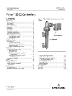
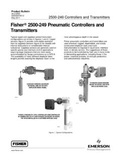
1 2500 249 Pneumatic Controllers andTransmittersFisher 2500, 2500C, 2500R, 2500S, 2500T, 2502,2502C, 2502F, and 2503 instruments are part of the2500 controller / transmitter series. Typical caged andcageless sensor/instrument configurations are shownbelow and in figure 1. Caged sensors (figure 2) providemore stable operation than do cageless sensors (figure3) for vessels with internal obstructions orconsiderable internal turbulence. Cageless sensors aregenerally used on specific gravity and interface controlapplications requiring large displacers that are moreeasily accommodated by flange connections up to NPS8. The availability of many different displacer stemlengths permits lowering the displacer down to themost advantageous depth in the Pneumatic Controllers and Transmitters are usedwherever rugged, dependable, and simply constructeddisplacer style Pneumatic instrumentation is requiredin liquid level, interface level, or density service.
2 Theruggedness of these products is demonstrated by theiruse in many kinds of demanding applications,including those in the power, chemical process, oil andgas production, and petrochemical CAGED SENSORSMOUNT ON VESSEL SIDEWITH DISPLACER INSIDE CAGEW8334W9354 1 Fisher 2500 controller INCOMBINATION WITH A 249W SENSOR CANMOUNT ON VESSEL TOP OR BE INSTALLED INA CUSTOMER SUPPLIED CAGEW8679 CAGELESS SENSORS CAN MOUNTON VESSEL SIDE OR TOP WITH DISPLACER INSIDE VESSEL2500-249 Controllers and TransmittersD200037X012 Product :2500 August 20182500-249 Controllers and TransmittersD200037X012 Product :2500 August 2018 2 SpecificationsAvailable ConfigurationsSee tables 1, 5, and 6 Input SignalFluid Level or Fluid to Fluid Interface Level: From 0 to100 percent of displacer length standard lengths forall sensors are J356 mm (14 inches) or J813 mm(32 inches); other lengths available depending onsensor constructionFluid Density: From 0 to 100 percent of displacementforce change obtained with given displacervolume standard volumes areJ980 cm3 (60 inches3) for 249C and 249CP sensorsor J1640 cm3 (100 inches3) for most other sensors.
3 Other volumes available depending upon sensorconstructionAllowable Specific GravitySpecific gravity with standard volume displacers andstandard wall torque tubes:Fluid Level and Fluid to Fluid Interface2500 Controllers , except 2503 and 2503R: Specificgravity range, to and 2503R: Specific gravity range, to Density2500 Controllers , except 2503 and 2503R: Minimumchange in specific gravity, and 2503R: Minimum change in specific gravity, your Emerson sales office or Local BusinessPartner for information on non standard applicationsOutput SignalSee table 1 Output ActionJ Direct (increasing fluid or interface level or specificgravity increases output pressure) orJ Reverse (increasing fluid or interface level orspecific gravity decreases output pressure)Area Ratio of Relay Diaphragms3:1 Supply Pressure(1)Normal Operation: See table to Prevent Internal Part Rupture(2).
4 3 bar (45 psig)Steady State Air ConsumptionSee table 4 Proportional Band, Differential Gap, or SpanSee table 1 Set Point ( Controllers Only)Continuously adjustable to position control point ordifferential gap of less than 100 percent anywherewithin displacer length (fluid or interface level) ordisplacement force change (density)Zero Adjustment ( Transmitters Only)Continuously adjustable to position span of less than100 percent anywhere within displacer length (fluidor interface level) or displacement force change(density)PerformanceIndependent Linearity ( Transmitters Only):1 percent of output pressure change at span of 100percentHysteresis: percent of output pressure change at100 percent of proportional band, differential gap, orspanRepeatability: percent of displacer length ordisplacement force changeDeadband (Except Differential Gap Controllers (3)) percent of proportional band or spanTypical Frequency Response: 4 Hz and 90 degreephase shift at 100 percent of proportional band,differential gap, or span with output piped to typicalinstrument bellows using meters (20 feet) of (1/4 inch) tubingAmbient Temperature Error.
5 Percent of outputpressure change per 28_C (50_F) of temperaturechange at 100 percent of proportional band,differential gap, or span when using sensor withstandard wall N05500 torque tubeReset (Proportional Plus Reset Controllers Only):Continuously adjustable from to over per repeat (from 200 to under repeatsper minute)Anti Reset Differential Relief (2502F and 2502 FRControllers Only): Continuously adjustable from bar (2 to 7 psi) differential to relieve excessivedifference between proportional and reset pressures continued 2500-249 Controllers and TransmittersD200037X012 Product :2500 August 2018 3 Specifications (Continued)Standard Tubing Connections1/4 NPT internalSensor Connection SizesSee tables 5 and 6 Maximum Working Pressures (Sensors Only)(1)Consistent with applicable ASME pressure/temperature ratings for the specific sensorconstructions shown in tables 5 and 6 Operative Ambient Temperatures(1) : -40 to 71_C (-40 to 160_F)JHigh Temperature.
6 -18 to 104_C (0 to 220_F) table 2 For ambient temperature ranges, guidelines, and useof optional heat insulator, see figure 4 Standard Supply and Output Pressure GaugeIndicationsSee table 4 Allowable Process Temperatures(1)See table 2 Hazardous Area Classification2500 Controllers comply with the requirements ofATEX Group II Category 2 Gas and DustMeets Customs Union technical regulation TP TC012/2011 for Groups II/III Category 2 equipmentII Gb c T*XIII Db c T*XConstruction MaterialsSee tables 2, 3, and 7 Mounting PositionsSee figure 9 Caged Sensor Connection StylesSee figure 10 OptionsSee Options sectionNOTE: Specialized instrument terms are defined in ANSI/ISA Standard - Process Instrument The pressure/temperature limits in this document and any applicable code or standard should not be Also see Supply Pressure Overpressure Protection For 2500S, 2500SC, and 2503 adjusting the differential gap is equivalent to adjusting the of ContentsSpecifications Pressure Overpressure Protection of Operation controller or Transmitter controller Windup controller With Proportional Valve controller Without Proportional Valve Information Controllers and TransmittersD200037X012 Product.
7 2500 August 2018 4 Table 1. Additional Specifications for Selected Fisher 2500 controller ConfigurationsControl or Transmission ModeController(1)Full Output Signal Change Obtainable Over Input Of:Output SignalProportional control2500, 2500C(2)Proportional band of 0 to 100 percent of displacer length ordisplacement force change (10 to 100 percent recommended) to bar(3 to 15 psig) to bar(6 to 30 psig)Proportional plus reset control2502, 2502C(2)Proportional band of 0 to 200 percent of displacer length ordisplacement force change (20 to 200 percent recommended)Proportional plus reset control withanti reset windup2502 FDifferentialGap (On off)ControlWith proportional valveand full differentialgap adjustment2500S, 2500SC(2)
8 Differential gap of 0 to 100 percent of displacer length0 and bar (0 and 20 psig) or0 and bar(0 and 35 psig)Without proportionalvalve - has limiteddifferential gapadjustment2503 Differential gap of approximately 25 to 40 percent of displacerlength, when a 356 millimeter (14-inch) ideal volume displacer isused on specific gravity liquid level service and a standard (20 psig) supply regulator setting is varied between and (15 and 25 psig)(3)0 and full supplypressure(4)Proportional transmission2500T, 2500TC(2)Span of 0 to 100 percent of displacer length or displacement forcechange (20 to 100 percent recommended) and bar (3 to 15 psig) or to bar (6 to 30 psig)1.
9 The suffix R is added to the type number for reverse action, and all types have a 67 CFR supply regulator mounted as The suffix C is added to the type number for indicator Other displacer lengths and volumes, or service conditions, will result in other differential bar (20 psig) and bar (35 psig) are the standard factory set supply regulator pressures, but these values will vary whenever the supply pressure is changed toadjust the differential 2. Allowable Process Temperatures forCommon Fisher 249 Sensor Component MaterialsMATERIALPROCESS TEMPERATUREM inimumMaximumCast Iron(1)-29_C (-20_F)232_C (450_F)Steel-29_C (-20_F)427_C (800_F)Stainless Steel-198_C (-325_F)427_C (800_F)N04400-198_C (-325_F)427_C (800_F)Aluminum-195_C (-320_F)99_C (210_F)GasketsGraphite Laminate/SSTN04400/PTFESoft Iron Gasket-198_C (-325_F)-73_C (-100_F)-29_C (-20_F)427_C (800_F)204_C (400_F)427_C (800_F)BoltingB7 steelB7M steelB8M stainless steel-46_C (-50_F)-29_C (-20_F)-198_C (-325_F)427_C (800_F)427_C (800_F)427_C (800_F)1.
10 Cast iron may be used to -73_C (-100_F) provided a heat insulator is usedbelow -18_C (0_F) and stainless steel studs and nuts are used below -46_C(-50_F).Table 3. Displacer and Torque Tube MaterialsPartStandard MaterialOther MaterialDisplacer304 Stainless Steel316 Stainless Steel,N10276, N04400,Plastic, and SpecialAlloysDisplacer Stem,Driver Bearing,Displacer Rod and Driver316 Stainless SteelN10276, N04400,other AusteniticStainless Steels, andSpecial AlloysTorque TubeN05500(1)316 Stainless Steel,N06600, N102761