Transcription of Fisher 3660 and 3661 Positioners - Pacific Controls
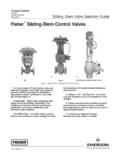
1 3660 and 3661 PositionersFisherR 3660 pneumatic (see figure 1) and 3661electro-pneumatic single-acting Positioners are usedwith various actuators on sliding-stem valves forthrottling applications. These rugged positionersprovide a valve position proportional to a pneumaticinput or a standard millampere DC input signalreceived from a control , Efficient, Vibration-ResistantOperation positioner design provides accurate,fast-responding instruments able to withstand thevibrations of most plant environments. Lowsteady-state air consumption contributes to Gain Easily adjustable gain anddamping adjustments fine tune the positionerstability to specific application positioner accepts a standardpneumatic input signal (3660) or a standardmilliampere DC input signal (3661) from a controldevice.
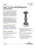
2 This positioner provides split rangecapabilities and adjustable zero and Spare Parts Required Most of theparts for 3660 and 3661 Positioners areinterchangeable, requiring fewer spare parts tosupport these Construction The case and coverare designed to withstand mechanical vibration andrough / ILFigure 1. FisherR 3660 positioner with Baumannt ActuatorDEasy positioner Adjustments Zero andspan adjustments can be made with the cover Valve Diagnostic TestingCapability To support diagnostic testing ofvalve/actuator/ positioner packages with theFlowScannert valve diagnostic system, connectors,piping, and other hardware can be installed betweenthe 3660 or 3661 positioner and the actuator.
3 Atypical connector installation is shown in figure :3660D101407X012 April 20093660 and 3661 Positioners3660 and 3661 PositionersProduct :3660 April 2009 2 SpecificationsAvailable Configuration3660: Single-acting pneumatic valve positioner3661: Single-acting electro-pneumatic valvepositionerInput Signal3660 to bar (3 to 15 psig), J to bar(6 to 30 psig), or JSplit range, see table 23661:J4-20 mA DC constant current with 30 VDCmaximum compliance voltage JSplit range isalso available, see table 2 Equivalent Circuit3661: 120 ohms shunted by three V zenerdiodesOutput SignalType: Pneumatic pressure as required by theactuator up to full supply pressureAction: JDirect (increasing input signalincreases positioner output), JReverse(increasing input signal decreases positioneroutput)Supply Pressure(1)Maximum: bar (90 psig)Recommended: 10% above actuatorrequirementsPerformanceIndepende nt Linearity: 1% of output : of output span(2).
4 Deadband: of input Compatiblity for 3661electro-pneumatic positioner :Meets EN 61326-1 (First Edition)Immunity Industrial locations per Table 2 ofthe EN 61326-1 standard. Performance isshown in table 1 Class AISM equipment rating: Group 1, Class APositioner AdjustmentsSpan: Adjustable from 19 mm to 50 mm ( to2 inches) stem : 0 to 100%.Gain: to 6% PB (proportional band)(3).Output Volume Damping: Loop dynamicresponse Capacity(4) Bar (20 Psig) Supply: normal m3/hour(150 scfh) Bar (35 Psig) Supply: normal m3/hour(230 scfh)Exhaust Capacity(4) Bar (20 Psig) Supply: normal m3/hour(170 scfh) Bar(35 Psig) Supply: normal m3/hour(260 scfh)Steady-State Air Consumption(4,5)3660: normal m3/hour ( scfh) at bar (20 psig) supply pressure.
5 Normalm3/hour ( scfh) at bar (35 psig) supplypressure3661: normal m3/hour ( scfh) at bar(20 psig) supply pressure. normal m3/hour( scfh) at bar (35 psig) supply pressureOperating InfluencesSupply Pressure: 69 mbar (1 psig) change insupply pressure changes the actuator stemposition less than (6) of the travelOperative Temperature Limits(1)3660 without Pressure Gauges: 40 to 121 C( 40 to 250 F)3660 with Pressure Gauges: 40 to 82 C ( 40to 180 F)3661 with or without Pressure Gauges: 40 to82 C ( 40 to 180 F)Hazardous Area Classification for 36603660 pneumatic Positioners comply with therequirements of ATEX Group II Category 2 Gasand Dust- continued -3660 and 3661 PositionersProduct.
6 3660 April 2009 3 Specifications (Continued)Hazardous Area Classification for 3661 Intrinsic Safety, Non-incendive, Type n Intrinsic Safety, Non-incendive, Type n Intrinsic Safety, Type n (Gas Atmospheres Only) Intrinsic Safety, Type n (Gas Atmospheres Only) Intrinsic Safety, Type nRefer to tables 6, 7, 8, 9, and 10 for Classification for 3661 CSA Type 3 Encl., NEMA 3, IP44 per IEC 60529,except FM / SAA, IP54 per IEC 60529; Mountingorientation requires vent location to be positioner can be mounted in one of fourdifferent configurations. See figure Connections1/4 NPT internalConduit Connection for 36611/2 NPT (M20 or PG13 adaptors optional)Maximum Valve Stem Travel50 mm (2 inch).
7 Adjustable to obtain lesser travelwith standard input signal minimum 19 mm( inch)Construction MaterialsSee table 4 Options3660:JInstrument and output pressure gauges,JIntegrally mounted bypass valve3661: Output pressure gauge3660 and 3661: Connectors for diagnostic testingJstainless steel or JbrassApproximate Weight3660: pounds ( kg)3661: pounds ( kg)Vent Connection1/4 NPT internalNOTE: Specialized instrument terms are defined in ANSI/ISA Standard Process Instrument The pressure/temperature limits in this bulletin and any applicable standard or code limitation should not be Hysteresis value at a gain setting of 1/2 Adjusting the gain (PB) adjustment will change the nozzle flapper relationship.
8 This nozzle flapper change affects the actuator/ positioner response Normal m3/hr--normal cubic meters per hour (0_C and bar absolute). Scfh--standard cubic feet per hour (60_F and psia).5. Air consumption at a gain setting of 1/2 At supply pressure of bar (35 psig).Table 1. FisherR 3661 Electro-Pneumatic positioner EMC Summary Results ImmunityPORTPHENOMENONBASIC STANDARDTEST LEVELPERFORMANCECRITERIA(1)EnclosureElec trostatic discharge(ESD)IEC 61000-4-24 kV contact8 kV airARadiated EM fieldIEC 61000-4-380 to 1000 MHz @ 10V/m with 1 kHz AM at 80%1400 to 2000 MHz @ 3V/m with 1 kHz AM at 80%2000 to 2700 MHz @ 1V/m with 1 kHz AM at 80%ARated power frequencymagnetic fieldIEC 61000-4-860 A/m at 50 HzAI/O signal/controlBurstIEC 61000-4-41 kVASurgeIEC 61000-4-51 kV (line to ground only, each)
9 BConducted RFIEC 61000-4-6150 kHz to 80 MHz at 3 VrmsASpecification limit = 1% of span1. A = No degradation during testing. B = Temporary degradation during testing, but is and 3661 PositionersProduct :3660 April 2009 4 ACTUATOR: AIR-TO-RETRACTPOSITIONER ACTION: DIRECT(INCREASING INPUT SIGNAL INCREASESOUTPUT PRESSURE TO ACTUATOR)INPUT SIGNALAIR SUPPLYOUTPUTPILOT SHAFT1 ACTUATOR: AIR-TO-RETRACTPOSITIONER ACTION: REVERSE(INCREASING INPUT SIGNAL DECREASESOUTPUT PRESSURE TO ACTUATOR)INPUT SIGNALAIR SUPPLYOUTPUTFEEDBACKPLATE2 ACTUATOR: AIR-TO-EXTENDPOSITIONER ACTION: REVERSE(INCREASING INPUT SIGNAL DECREASESOUTPUT PRESSURE TO ACTUATOR)INPUT SIGNALAIR SUPPLYOUTPUT1 ACTUATOR.
10 AIR-TO-EXTENDPOSITIONER ACTION: DIRECT(INCREASING INPUT SIGNAL INCREASESOUTPUT PRESSURE TO ACTUATOR)INPUT SIGNALAIR SUPPLYOUTPUT2 NOTES:WHEN MOUNTING ON BAUMANN ACTUATORS, INSTALL FEEDBACK PLATE SO LIP IS UP. INSTALL FEEDBACK LEVER ARMASSEMBLY SO PILOT SHAFT IS ON TOP OF THE FEEDBACK MOUNTING ON BAUMANN ACTUATORS, INSTALL FEEDBACK PLATE SO LIP IS DOWN. INSTALL FEEDBACK LEVER ARMASSEMBLY SO PILOT SHAFT IS UNDERNEATH THE FEEDBACK / ILFigure 2. Mounting Configurations (see table 3 for positioner Action and Signals)3660 and 3661 PositionersProduct :3660 April 2009 5 Table 2.