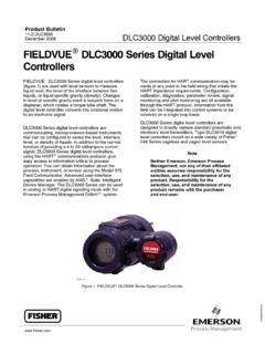
Transcription of Fisher 4320 Wireless Position Monitor - Pacific …
1 4320 Wireless Position MonitorThe Fisher 4320 Wireless Position Monitor is anon contacting Wireless Position transmitter and limitswitch. It is a rugged measurement device thatprovides a precise Wireless feedback signal toindicate equipment Position with a percent (%) ofspan plus on/off indication. The 4320 can be used tomonitor equipment such as valves, sliding stemregulators, displacement and float level sensors, andrelief valves. It is designed to be simple to use,compact, and easily Wireless Position Monitor periodically reads theposition of a measured device and transmits thatdata over the Wireless network. The transmitted dataincludes the percent of span value, two limit switchstatus indications, internal device temperatures, andpower module voltage. It also checks for service andconfiguration instructions from host systems such asdistributed control systems (DCS), assetmanagement systems (AMS), and supervisorycontrol and data acquisition (SCADA) 4320 Wireless Position Monitor is poweredprimarily by a power module, eliminating the need toinstall wires.
2 This makes it easier to design newapplications or implement into retrofit , the elimination of levers and linkagesreduces the number of mounting parts and mountingcomplexity. Replacement and maintenance aresimplified because the feedback parts stay with themeasured 4320 Wireless Position Monitor uses a highperformance linkage less feedback design thateliminates direct contact with the measured device( , valve, regulator, level, louver, or other devices)eliminating physical contact and communication protocol operatingat is utilized and is approved for 1 Figure 1. Fisher 4320 Position MonitorInstrument calibration and commissioning isperformed with a push button and liquid crystaldisplay (LCD) interface. The interface is protectedfrom the environment within a sealed enclosure. Theinterface supports multiple languages, includingGerman, French, Italian, Spanish, Chinese, Czech,Japanese, English, Russian, Korean, and to meet intrinsically safe andnon incendive requirements, this instrument deliversscalable functionality in a small package.
3 The powermodule option has no cable conduits. Due to theenergy limiting nature of the design, this intrinsicallysafe device is suitable for use in all zone 4320 provides a percent of span, as well astwo independent limit switch equivalent feedbacksignals typically used with modulating :4320D103286X012 May 20104320 Wireless Position Monitor4320 Wireless Position MonitorProduct :4320 May 2010 2 SpecificationsAvailable MountingsJ Quarter turn rotary shaft J Sliding stem orJ Linear applicationsCan also be mounted on other actuators thatcomply with IEC 60534 6 1, IEC 60534 6 2,VDI/VDE 3845 and NAMUR mounting MeasurementStem TravelMinimum: mm ( inch)Maximum: 102 mm (4 inches)Shaft RotationMinimum: 45_Maximum: 90_Measurement OutputAnalog: 0 100%Discrete: on/off switches (2)Reference Accuracy2% of spanLocal User InterfaceLiquid Crystal Display (LCD)Two pushbuttons for navigation, setup, andcalibrationInput Communication SignalWirelessHART communicationHART VariablesVariableVariable NamePrimary (PV)Percent (%) of SpanSecondary (SV)Closed TriggerTertiary (TV)Open TriggerQuaternary (QV)Internal TemperatureVariable #5 Power Module VoltageOutput Communication Ghz, DSSS, WirelessHARTM aximum 10 dBm EIRP at GHz, 10 mW EIRP at GHzWireless ClassificationsClass A digital device, complies with part 15 of theFCC RulesContains FCC ID: LWZRM2510 Contains IC: 2731A RM2510 Electromagnetic CompatibilityMeets EN 61326-1 (First Edition)Immunity Industrial locations per Table 2 ofthe EN 61326-1 standard.
4 Performance isshown in table 1 Class A & B. Performance isshown in table 2 equipment rating: Group 1, Class A & BEuropean Directive InformationThis product complies with the followingdirectives:ATEX Directive (94/9/EC)Electro Magnetic Compatibility (EMC)(2004/108/EC)Radio and Telecommunications TerminalEquipment Directive (R&TTE) (1999/5/EC)Refer to the Safety Instructions (D103022X012)for the Declaration of ConformityOperating Temperature Limits(1) 40 to 80_C ( 40 to 176_F) LCD may not be readable below 20_C ( 4_F)Temperature change per degree CStorage Temperature Limits(1)Upper limit not to exceed 100_C (212_F)Humidity Limits10 95% Condensing Relative Humidity continued 4320 Wireless Position MonitorProduct :4320 May 2010 3 Specifications (continued)Electrical ClassificationCSA (C/US) Intrinsically SafeATEX Intrinsically SafeIECEx Intrinsically SafeRefer to table 3 and 4 for additional informationElectrical HousingCSA (C/US) 4X & IP66 ATEX 4X & IP66 IECEx 4X & IP66 IEC 61010 ComplianceMeets Pollution Degree 2 AdjustmentsZero and Maximum Span through local interfaceDimensionsSee figure Kg ( lbs)Power ModuleStandardLithium (non rechargeable)Power Module LimitsStandard 5 years @ 1 minute update rate with3 additional devices communicating through itExtended Life 6 years @ 4 second updaterate with 3 additional devices communicatingthrough itShelf life 15 years (radio off)Update RatesFor Position feedback, temperature, and powermodule voltage selectable from 4 seconds to 1hour, 4s, 8s, 16s, 32s, 1 to 60 minutesFactory default is 1 minuteConstruction MaterialHousing: Engineered resin1.
5 The temperature limits in this document and any applicable standard or code limitation for valve should not be Contact your Emerson Process Management sales office for information on pending third party 1. EMC Summary Results ImmunityPortPhenomenonBasic StandardTest LevelPerformanceCriteria(1)EnclosureElec trostatic discharge (ESD)IEC 61000-4-26 kV contact8 kV airBRadiated EM fieldIEC 61000-4-380 to 1000 MHz @ 3V/m with 1 kHz AM at 80%1400 to 2000 MHz @ 3V/m with 1 kHz AM at 80%2000 to 2700 MHz @ 3V/m with 1 kHz AM at 80%ARated power frequencymagnetic fieldIEC 61000-4-8100 A/m at 50 Hz & 60 HzAPerformance criteria: +/ 2% of effect1. A = No degradation during testing. B = Temporary degradation during testing, but is Wireless Position MonitorProduct :4320 May 2010 4 Table 2. EMC Summary Results EmissionsPortFrequencyRange (MHz)BasicStandardEmissions LevelGiven RatingEnclosure30 to 230EN 55011 Group 1 Class A: 40 dB (uV/m) measured at 10 m distanceGroup 1 Class B: 30 dB (uV/m) measured at 10 m distanceClass A & B230 to 1000 Group 1 Class A: 47 dB (uV/m) measured at 10 m distanceGroup 1 Class B: 37 dB (uV/m) measured at 10 m distanceClass A & B1000 to 3000 Group 1 Class B50 dB (uV/m) measured at 3 m distance, peak limit not to exceed 70 dB (uV/m)Class A & B3000 to 6000 Group 1 Class B54 dB (uV/m) measured at 3 m distance, peak limit not to exceed 74 db (uV/m)Class A & BNOTES:The 4320 is considered as a Group 1 , Scientific, and Medial (ISM) radio frequency (RF) equipment is rated according to its Group and Class as follows.
6 Group I Equipment in which there is intentionally generated and/or used conductively coupled radio frequency energy which is necessary for the internal functioning of the II Equipment in which radio frequency energy is intentionally generated and/or used in the form of electromagnetic radiation for the treatment of material, and EDM and arcwelding A Equipment suitable for use in industrial and commercial environmentsClass B Equipment suitable for use in domestic environmentsTable 3. Hazardous Area Classifications CSA (Canada and United States)Certification BodyCertification ObtainedEntity RatingTemperature CodeEnclosure RatingCSAEx ia Intrinsically SafeCL I, Div I, GP ABCD T3/T4/T5Ex ia IIC T3/T4/T5 Class I Zone 0 AEx ia IIC T3/T4/T5 HART Terminals WP1/WP2T3(Tamb v 80_C)T4(Tamb v 75_C)T5(Tamb v 40_C)4X & IP66 Vmax (Ui) = (Ii) = 5mACi = nFLi = 0 Voc (Uo) = (Io) = 14mACa (Co) = 42mFLa (Lo) = 150mHTable 4. Hazardous Area Classifications ATEX and IECExCertificationCertification ObtainedEntity RatingTemperature CodeEnclosure RatingATEXIECExIntrinsically SafeEx ia IIC T3/T4/T5 GaHART Terminals WP1/WP2T3(Tamb v 80_C)T4(Tamb v 75_C)T5(Tamb v 40_C)4X & IP66Ui = = 5mAPi = = = 0Uo = = 14mAPo = = 42mFLo = 150mH4320 Wireless Position MonitorProduct :4320 May 2010 5 FeaturesDReliable Wireless The WirelessHART self organizing mesh network provides the highlevel of communication reliability required in Maintenance The sensing designprovides more accurate monitoring and eliminatesphysical wear out common in traditional limitswitches and Position transmitters.
7 This results inless frequent maintenance, repair, andre calibration. The standard version of this deviceuses a power module with expected module lifemeeting typical maintenance of Implementation No conduiteasements or permits are required, thus saving time,costs, and effort in documenting cable runs andassociated design reviews. Because there is nowiring, implementation times are shortened fordevice installation, setup, and the reduction is from months to Construction The housing is madefrom engineered resin, making it a good solution formost locations, including corrosive Predefined device, network, andsystem diagnostics provide details on the health ofthe device and its ability to communicate. Devicediagnostics include whether the device calibrationhas been completed and power module health. Thenumber of completed cycles is measured for themonitored cycle is the change from open toclosed Position or vice versa. This isdetermined by moving past the triggerpoint in each The WirelessHART self organizingmesh network includes encryption, authentication,and authorization mechanisms to provide the level ofsecurity required in process locations and by theInformation Technology (IT) the 4320 Wireless Position monitoroperates with WirelessHART communications it canbe used for incremental monitoring applications.
8 Thisreplaces manual efforts to audit or verify equipmentposition during normal operations, such as startupand shutdown situations, product changeover,product isolation, and sampling implementation method can be accomplishedusing an overlay approach; adding wirelessinstrumentation on top of existing preserves the existing infrastructure andenables improved information for operation,reactiveness, maintenance, and second approach is to replace older limit switchesand Position transmitters, either because ofincreased maintenance requirements or dated wiringinfrastructure that has become or is believed tobecome an operational third approach is to use the 4320 where feedbackis not possible with standard wired options. Forexample, on rotating equipment, where theelimination of wires makes feedback Wireless nature of this device leads to itsimplementation in a wide range of systems, fromprogrammable logic controllers (PLC), to DCS, AMS,and SCADA integration for typical in plant operations isavailable through the Smart Wireless 1420 of OperationThe internal electronics periodically reads theposition of travel and transmits that data over thewireless network.
9 The device also checks forinstructions from host systems like DCS, SCADAand asset management systems. The device sleeps until the next reading, enabling longerpower module life. The device is still powered up inthe sleep mode but operating at ultra low powerconsumption Wireless Position MonitorProduct :4320 May 2010 6 Setup/InstallationDevice setup is typically performed prior toinstallation and includes setting two networkparameters. These parameters are entered using ahandheld such as the 475 or 375 FieldCommunicator. Calibration is performed afterinstallation and requires using the local interface toplace the device at the end points of travel device is then ready for commissioning Module LifeThe 4320 Position Monitor uses power efficientmeasures to keep energy consumption to aminimum. However, there is a finite amount ofenergy within the power module. The life expectancyof the module is affected by two things; 1) thereporting rate, and 2) the number of devices in thenetwork that must communicate through the 4320position on/off applications will operate effectively atone minute reporting InformationWhen ordering, specify:1.
10 Position Monitor type Mounting requirements;Feedback sensor and mounting brackets are part ofthe rotary movement indicate if mountingrequirements are:D90_ NAMUR, orD90_ ISO mountingFor linear movement, indicate travel length:D1, 2, or 4 inch strokesDContact your Emerson Process Managementsales office if longer travel lengths are requiredDContact your Emerson Process Managementsales office if mounting on non Emerson valves isrequiredNoteNeither Emerson, Emerson ProcessManagement, nor any of their affiliatedentities assumes responsibility for theselection, use, or maintenance of anyproduct. Responsibility for theselection, use, and maintenance of anyproduct remains with the purchaserand end Wireless Position MonitorProduct :4320 May 2010 ( ) ( ) ( ) ( )67( ) ( ) ( ) ( )157( ) ( ) ( ) ( ) ( ) ( ) ( ) ( )GE41356 B6X M6 18 mm MAXIMUM ALLOWABLETHREAD ENGAGEMENTmm(INCH) ( ) ( ) ( ) ( ) ( ) ( )87( )ANTENNA SHOWN VERTICALANTENNA SHOWN HORIZONTALF igure 2.

