Transcription of Fisher 657 Diaphragm Actuator Sizes 30/30i …
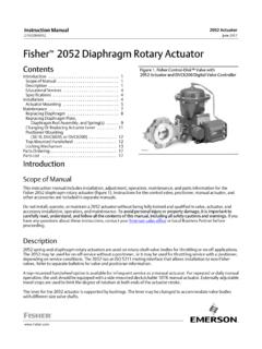
1 657 Diaphragm ActuatorSizes 30/30i through 70/70i and of the Actuator on the of Bench the Stem Connector Mounted Handwheel Mounted Handwheel for Sizes 34/34ithrough 60/60i Mounted Handwheel for Sizes 70and 87 Mounted Adjustable Travel for Side Mounted for Top Mounted Assembly (figures 6, 7, 8, 9, or 10) 1. Fisher 657 Actuator Mounted on an easy e ValveX1175 Top Mounted Handwheel (figures 11 or 12) Mounted Handwheel (figure 13 or 17) Mounted Adjustable Up Travel Stops(figures 18 or 19) Mounted Adjustable Down Travel Stops(figure 20) of ManualThis instruction manual provides information on installation, adjustment, maintenance, and parts ordering for theFisher 657 Actuator in Sizes 30/30i through 70/70i and size 87. The 657 4 Actuator in Sizes 70/70i and 87 is alsocovered. Refer to separate instruction manuals for information about the valve positioner and other accessories usedwith these not install, operate, or maintain a 657 Actuator without being fully trained and qualified in valve, Actuator , andaccessory installation, operation, and maintenance.
2 To avoid personal injury or property damage, it is important tocarefully read, understand, and follow all the contents of this manual, including all safety cautions and warnings. If youhave any questions about these instructions, contact your Emerson sales office or Local Business Partner ManualD100306X012657 Actuator ( 30/30i -70/70i and 87)June 2018 Instruction ManualD100306X012657 Actuator ( 30/30i -70/70i and 87)June 20182 Table 1. SpecificationsSPECIFICATION(1) Actuator SIZE30/30i34/34i40/40i45/45i46/46i50/50i 60/60i70/70i(1)87(1)Nominal Effective Areacm22974454456771006677100614191419 Inch2466969105156105156220220 Yoke Boss Diametersmm5454717171909090127 Inches2 1/82 1/82 13/162 13/162 13/163 9/163 9/163 9/165 Acceptable ValveStem AllowableOutput Thrust(4)N102301023012010251313358225131 302463914239142Lb23002300270056507550565 0680088008800 Maximum Travel(2)mm1929385151515176(3)76(3) (3)3(3)Maximum CasingPressure forActuator Sizing(4) DiaphragmCasing Pressure(4)(5) TemperatureCapabilities_CNitrile Elastomers: -40 to 82_C, Silicone Elastomers: -54 to 149_C, Fluorocarbons: -18 to 149_C_FNitrile Elastomers: -40 to 180_F, Silicone Elastomers: -65 to 300_F, Fluorocarbons.
3 0 to 300_FPressure Connections(internal)1/4 NPTXXXXXXX 1/2 NPT XXApproximate Weightskg16/1722/2523/2537/4049/5242/455 3/56107/109116Lb36/3848/5451/5682/84107/ 11492/99116/125235/2402551. These values also apply to the 657 4 Actuator Actuator travel may be less than the value listed after connecting the Actuator to the Maximum travel for 657 4 is 102 mm (4 inches).4. Normal operating Diaphragm pressure must not exceed maximum Diaphragm casing pressure and must not produce a force on the Actuator stem greater than the maximum allowable out put thrust or the maximum allowable valve stem load. Contact your Emerson sales office or Local Business Partner with questions concerning maximum allowable valve stem This maximum casing pressure is not to be used for normal operating pressure. Its purpose is to allow for typical regulator supply settings and/or relief valve 657 Actuator (figure 1) and the 657 4 Actuator are direct acting, spring opposed Diaphragm actuators.
4 Theyprovide automatic operation of control valve body assemblies. The 657 Actuator offers 76 mm (3 inches) maximumactuator travel. The 657 4 Actuator provides 102 mm (4 inches) maximum Actuator travel. Both actuators position thevalve plug in response to varying pneumatic loading pressure on the Actuator Diaphragm . Figure 2 shows theoperation of these 657 or 657 4 Actuator can be equipped with either a top mounted or a side mounted handwheel assembly. Atop mounted handwheel assembly is used as an adjustable up travel stop to limit Actuator travel in the up direction(see figure 2). A side mounted handwheel assembly is usually used as an auxiliary manual Actuator . Adjustablecasing mounted up or down travel stops are also available for this repeated or daily manual operation is expected, the Actuator should be equipped with a side mounted handwheel rather than acasing mounted travel stop or top mounted side mounted handwheel is designed for more frequent use as a manual to table 1 for Specifications of the 657 and 657 4 actuators.
5 See the Actuator nameplate for specific informationabout your ManualD100306X012657 Actuator ( 30/30i -70/70i and 87)June 20183 Figure 2. Schematic of Fisher 657 and 657 4 ActuatorsSPRING LIFTSSTEM UPAIR PUSHESSTEM DOWNSTEMAF3833 AA0792 2 Educational ServicesFor information on available courses for Fisher 657 Diaphragm actuators, as well as a variety of other products,contact:Emerson Automation SolutionsEducational Services - RegistrationPhone: 1-641-754-3771 or 1-800-338-8158E-mail: VideosClick here or access the following QR code for a video on mounting a DVC6200 Digital ValveController on a 657 here or access the following QR code for a video on installing a side-mounted handwheel on a 657 number locations are shown in figures 6, 7, 8, 9, and 10, unless otherwise indicated. Also, refer to figure 3 forlocation of parts. WARNINGA lways wear protective gloves, clothing, and eyewear when performing any installation operations to avoid with your process or safety engineer for any additional measures that must be taken to protect against installing into an existing application, also refer to the WARNING at the beginning of the Maintenance section in thisinstruction ManualD100306X012657 Actuator ( 30/30i -70/70i and 87)June 20184 CAUTIONTo avoid parts damage, do not use an operating pressure that exceeds the Maximum Diaphragm Casing Pressure (table 1)or produces a force on the Actuator stem greater than the Maximum Allowable Output Thrust (table 1) or the maximumallowable valve stem load.
6 (Contact your Emerson sales office or Local Business Partner with questions concerningmaximum allowable valve stem load.)D Valve/ Actuator Assembly: If the Actuator and valve are shipped together as a control valve assembly, it has beenadjusted at the factory, and may be installed in the pipeline. After installing the valve in the pipeline, refer to theLoading Connection Actuator Mounting: If the Actuator is shipped separately or the Actuator has been removed from the valve, theactuator should be mounted to the valve before placing the valve in the pipeline when practical. In the case ofneeding to place a weld-end body in-line, the trim will be removed from the body during the welding process. Whencompleted and reassembled, the Actuator should then be mounted to the welded in valve assembly. Refer to theactuator mounting procedures before placing the valve in service.
7 You may perform the Bench Set SpringAdjustment procedures in this section to confirm the adjustment has not changed since it was shipped from Positioner: If a positioner is installed, or is to be installed on the Actuator , refer to the positioner instruction manualfor installation. During the adjustment procedures, it will be necessary to provide a temporary loading pressure tothe Actuator the Actuator on the ValveThe 657 Actuator spring loading pushes the Actuator stem up towards the Actuator Diaphragm (see figure 2). Thisspring action moves the stem away from the valve while installing the the valve stem is allowed to remain in the up position (towards the Actuator ) during mounting, it can interfere with theactuator mounting, possibly damage valve stem threads or bend the valve stem. Be sure the valve stem is pushed down(into the valve body), away from the Actuator while a temporary method of applying Diaphragm loading pressure to the Diaphragm to extend the Actuator stemduring bench set spring Provide a vise or some other method of supporting the valve and the weight of the Actuator during assembly.
8 Fordirect or reverse acting valves, push the valve stem down away from the Actuator while mounting the Screw the stem locknuts all the way onto the valve stem. With the concave side of the travel indicator disk (key 14)facing the valve, install the travel indicator disk on the valve stem. (Note: The travel indicator disk is not used withsize 87 actuators.)3. Lift or hoist the Actuator onto the valve bonnet:a. For size 87 actuators, insert the cap screws and tighten the hex nuts, securing the Actuator to the For all other size actuators, screw the yoke locknut onto the valve bonnet and tighten the locknut. (Note: Onsmall size actuators, it may be necessary to remove the indicator disk and re install it while lowering the actuatoron to the valve because the disk will not go through the Actuator yoke opening.)Instruction ManualD100306X012657 Actuator ( 30/30i -70/70i and 87)June 201854.
9 Do not connect the Actuator stem to the valve stem at this time. Whenever the Actuator is installed on the valve, itis recommended to perform the Bench Set Spring Adjustment procedure to verify that the Actuator is still 3. Actuator Mounting Components for size 30/30i through 70/70i ActuatorsVALVE STEMYOKE LOCK NUTYOKE BOSSDIAMETERBONNETTYPICAL VALVE(REFER TO VALVEMANUAL)W6199-1 MATCHLINE FORACTUATORNPT INTERNAL CONNECTIONDIAPHRAGM CASINGDIAPHRAGM AND STEM SHOWNIN UP POSITIONDIAPHRAGM PLATEACTUATOR SPRINGACTUATOR STEMSPRING SEATSPRING ADJUSTORSTEM CONNECTORYOKETRAVEL INDICATOR DISKINDICATOR SCALEX1177 LOWER Diaphragm CASINGX1176 size 30i THROUGH 70iSIZE 30 THROUGH 70 INTEGRATED FIELDVUE DVC6200 ANDDVC2000 DIGITAL VALVE CONTROLLERMOUNTING PADINTEGRATEDSIDE-MOUNTEDHANDWHEELMOUNTI NGPADS (4)Discussion of Bench SetThe bench set pressure values are used to adjust the initial compression of the Actuator spring with the valve actuatorassembly on the bench.
10 The correct initial compression is important for the proper functioning of the valve actuatorassembly when it is put into service and the proper Actuator Diaphragm operating pressure is bench set values are established with the assumption that there is no packing friction. When attempting to adjustthe spring in the field, it is very difficult to ensure that there is no friction being applied by loose ManualD100306X012657 Actuator ( 30/30i -70/70i and 87)June 20186 Accurate adjustment to the bench set range can be made during the Actuator mounting process by making theadjustment before the Actuator is connected to the valve (see the Spring Verification procedure).Figure 4. Bench Set AdjustmentSPRING ADJUSTERLOWER BENCH SETLOADING PRESSUREUPPER BENCH SETPRESSURE MARKVALVESTEMRATED VALVETRAVEL MEASUREMARKVALVESTEM HEREUPPER BENCH SETLOADING PRESSUREACTUATOR STEMNOTES: THE LOWER PSIG LOADING PRESSURE (MARKED ON NAMEPLATE) WHERE THE FIRST MOVEMENT OF Actuator STEM IS DETECTED.