Transcription of Fisher 8532 High-Performance Butterfly Valve - Emerson
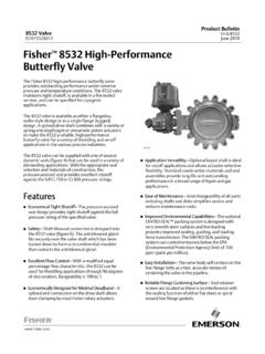
1 8532 High-Performance Butterfly of Installing the the Actuator Travel Stops or the Adjustment and Shaft and Replacing the the , Phoenix III and/orPhoenix III Fire Tested Blowout Design, Packing, Valve Shaft,Disk, and Bearing the Two Piece 1. Fisher 8532 valve with 1061 Actuator andFIELDVUE DVC6200 Digital Valve ControllerW9138-1 IntroductionScope of ManualThis instruction manual provides installation, maintenance, and parts information for NPS 14 through 48 Fisher 8532high- performance Butterfly not install, operate, or maintain an 8532 valve without being fully trained and qualified in Valve , actuator, andaccessory installation, operation, and maintenance. To avoid personal injury or property damage, it is important tocarefully read, understand, and follow all the contents of this manual, including all safety cautions and warnings.
2 If youhave any questions about these instructions, contact your Emerson sales office or Local Business Partner Valve is available in either a wafer (flangeless), lugged (single flange), or double flange body design, with a varietyof seals and internal components. The pressure assisted seal provides tight shutoff. The spline or keyed drive shaftcombines with a variety of actuators. Maximum inlet pressure/temperature ratings are consistent with CL150 ManualD101550X0128532 ValveJune 2018 Instruction ManualD101550X0128532 ValveJune 20182 Table 1. SpecificationsValve Size and End Connection StylesJNPS 14, J16, J18, J20, J24, J30, J36,J42, or J48 valves in Jwafer (flangeless),Jlugged (single flange), or Jdouble flange valvebodies with raised face flanges, CL150 or CL300 Maximum Pressure Drop(1)Consistent with CL150 and CL300pressure/temperature ratings per ASME 30-48: CL150/150 construction has CL150 ratedpressure retaining parts and 150 psid rated trimShutoff Classification Per ANSI/FCI 70 2 and IEC60534 4 Standard Soft Seal: Bidirectional shutoff Class VI(bubble tight)NOVEX Seal: Unidirectional shutoff Class IV (preferredflow direction only(3)), Class VI optional (excludingNPS 42 and 48)Phoenix III Seal: Bidirectional shutoff Class VI(bubble tight)Phoenix III Seal for Fire Tested Applications.
3 Unidirectional shutoff Class VI (reverse flow directiononly) (bubble tight). Fire Tested per API 607 Rev. more information contact your Emerson salesoffice or Local Business : For cryogenic seal applications, consultyour Emerson sales office or Local Business Seal ConfigurationsStandard ConstructionsSee figure 2 and table 2 Standard Construction MaterialsSee table 2 Flow CharacteristicModified equal percentageFlow CoefficientsSee Fisher Catalog 12 Flow Coefficient Ratio(2)100 to 1 Noise LevelsSee Fisher Catalog 12 for sound/pressure levelpredictionValve Body ClassificationWafer and Lugged face to face dimensions are incompliance with MSS SP68 and API 609 standardsthrough NPS 24. Double Flange Valve bodies complywith API 609 short face-to-face dimensions. Valvebodies are designed for installation between CL150 and CL300 raised face flangesDisk RotationClockwise to close (when viewing from the drive shaftend) through 90 degrees rotationShaft Diameter and Approximate WeightSee tables 4 and 5 ENVIRO SEAL PackingThis optional packing system provides improvedsealing, guiding, and transmission of loading force tocontrol liquid and gas emissions.
4 Contact yourEmerson sales office or Local Business Partner foravailability of ENVIRO SEAL packing1. The pressure/temperature limits in this manual, and any applicable code or standard limitation should not be Ratio of maximum flow coefficient to minimum usable flow coefficient may also be called For optimum seal performance , the preferred Valve orientation at shutoff is with the retaining ring downstream from the high pressure side of the ServicesFor information on available courses for Fisher 8532 valves , as well as a variety of other products, contact: Emerson Automation SolutionsEducational Services - RegistrationPhone: 1-641-754-3771 or 1-800-338-8158E-mail: ManualD101550X0128532 ValveJune 20183 Table 2. Material Temperature RatingsCOMPONENT AND MATERIAL OF CONSTRUCTION(1)TEMPERATURE RANGE_C_FValve Body(2)Carbon Steel (WCC or SA 516-70)(7)CF8M (316 SST)CF8M/CF10M (316/316H)(3) Dual-Certified-29 to 427-198 to 538over 538 to 816-20 to 800-325 to 1000over 1000 to 1500 DiskCF8M (316 SST)CF8M/CF10M (316/316H)(3) Dual-Certified-198 to 538over 538 to 816-325 to 1000over 1000 to 1500 Disk CoatingChromium CarbideChrome PlatingChromium Coating-198 to 916-254 to 427-254 to 593-325 to 1500-425 to 800-425 to 1100 ShaftS20910S17400 (17-4 pH 1025)N07718N07750N05500-198 to 538-73 to 427-254 to 704over 593 to 816-198 to 482-325 to 1000-100 to 800-425 to 1300over 1100 to 1500-325 to 900 Bearings(6)PEEK (standard)S31600(4)R30006 (Alloy 6)
5 Bronze-73 to 260-198 to 816-198 to 816-254 to 302-100 to 500-325 to 1500-325 to 1500-425 to 575 PackingPTFE Packing and PTFE ENVIRO-SEAL PackingGraphite packingGraphite packing with oxidizing mediaGraphite ENVIRO-SEAL Packing-148 to 232-198 to 916-198 to 538-148 to 315-325 to 450-325 to 1500-325 to 1000-325 to 600 Seal Ring andBackup RingPTFE Seal RingNitrile Backup O-RingChloroprene Backup O-RingEPR Backup O-RingFluorocarbon Backup O-RingPTFE Backup O-Ring-29 to 93-43 to 149-54 to 182-29 to 204-73 to 204-20 to 200-45 to 300-65 to 360-20 to 400-100 to 400 UHMWPE(5) Seal Ring (CL150 Only)EPR Backup O-RingFluorocarbon Backup O-Ring-54 to 93-29 to 93-65 to 200-20 to 200 Phoenix III and/or Fire Tested ConstructionS31600 and PTFE Seal Ring with Nitrile Backup O-RingChloroprene Backup O-RingEPR Backup O-RingFluorocarbon Backup O-Ring-40 to 149-54 to 149-62 to 204-40 to 232-40 to 300-65 to 300-80 to 400-100 to 200 Seal RingNOVEX S31600 Seal(4) Ring (CL150)NOVEX S31600 Seal(4) Ring (CL300)NOVEX S21800 Seal(4) Ring (CL300)-29 to 538-29 to 816-29 to 816-20 to 1000-20 to 1500-40 to 1500 Cryogenic Seal RingContact your Emerson Sales office or Local Business Partner1.
6 NACE trim constructions are available; consult your Emerson sales Special gasket retainer bolts are required for over 482_C (900_F)3. Special retaining ring screws for lugged valves over 538_C (1000_F)4. For a complete material description, contact your Emerson sales UHMWPE stands for ultra high molecular weight Special thrust bearings are required for high temp. applications over 343_C (650_F) (with 6- and 12-inch shaft extensions). Constructions with carbon steel valves and SST disks may requirespecial thrust bearings at temperatures less than 343_C (650_F).7. Cast or wrought /plate grades used interchangeably, depending upon availability - unless requested by ManualD101550X0128532 ValveJune 20184 InstallationThe Valve is normally shipped as part of a control Valve assembly, with the power actuator mounted on the Valve .
7 If thevalve or actuator has been purchased separately, or if the actuator has been removed for maintenance, mount theactuator on the Valve , and adjust actuator travel before installing the Valve into the line. This is necessary due to themeasurements that must be made during the actuator calibration adjustment process. Refer to the ActuatorMounting section of this manual and to the separate actuator instruction manual for mounting and adjustinginstructions before proceeding. WARNINGTo avoid personal injury or property damage resulting from the sudden release of pressure:D Do not remove the actuator from the Valve while the Valve is still Always wear protective gloves, clothing, and eyewear when performing any maintenance Do not install the Valve assembly where service conditions could exceed the limits given in this manual or on Use pressure relieving devices as required by government or accepted industry codes and good engineering practicesto protect from over pressurizing the Check with your process or safety engineer for any other hazards that may be present from exposure to process If installing into an existing application, also refer to the WARNING at the beginning of the Maintenance section in thisinstruction ordered, the Valve configuration and construction materials were selected to meet particular pressure.
8 Temperature,pressure drop, and controlled fluid conditions. Responsibility for the safety of process media and compatibility of valvematerials with process media rests solely with the purchaser and end user. Since some body/trim material combinationsare limited in their pressure drop and temperature ranges, do not apply any other conditions to the Valve without firstcontacting your Emerson sales office or Local Business Isolate the control Valve from the line pressure, release pressure from both sides of the Valve body, and drain theprocess media from both sides of the Valve . If using a power actuator, shut off all pressure lines to the poweractuator, release pressure from the actuator, and disconnect the pressure lines from the actuator. Use lock outprocedures to be sure that the above measures stay in effect while you are working on the the WARNING at the beginning of the Maintenance section for more information before removing the Valve fromthe Install a three Valve bypass around the control Valve assembly if continuous operation is necessary duringinspection and maintenance of the Inspect the Valve to be certain that it is free of foreign Be certain that adjacent pipelines are free of any foreign material, such as pipe scale or welding slag.
9 That coulddamage the Valve sealing to the disk will occur if any pipe flanges or piping connected to the Valve interfere with the disk rotation inside diameters for flanges or pipe mating with valves are shown in tables 4 and ManualD101550X0128532 ValveJune 20185 Valve OrientationThe Valve can be installed in any orientation, however it is recommended that the Valve drive shaft be horizontal andthe actuator vertical as shown in figure the Valve with the high pressure shutoff side in the direction noted by the flow arrow for proper installation, andsee figure 4 for more Installing the Valve WARNINGThe edges of a rotating Valve disk (key 2, figure 10 or 11) close with a shearing, cutting motion. To avoid personal injury,keep hands, tools, and other objects away from the disk while stroking the the 8532 valve is equipped with a fail open actuator, cycle the Valve into the fully closed position.
10 Ensure the Valve cannotopen during installation by using travel stops, a manual actuator, a constant supply pressure to the pneumatic actuator, orother steps as 3. Valve Body Data, CL150 Valve SIZE,NPSSHAFT DIA. ATYOKE BEARINGFACE TO FACE DIMENSION(1) (2)APPROXIMATE WEIGHT, KILOGRAMSW afer SIZE,NPSSHAFT DIA. ATYOKE BEARINGFACE TO FACE DIMENSION(1) (2)APPROXIMATE WEIGHT, POUNDSW afer andLuggedDouble-FlangeInchesWaferLuggedD ouble-Flange141 3 1 3 1 Face to face dimensions are in compliance with MSS SP68 and API 609 Minimum is the minimum pipe or flange required for disk swing clearance. Applies to wafer and lugged Valve bodies ManualD101550X0128532 ValveJune 20186 Table 4. Valve Body Data, CL150/150 Valve SIZE,NPSSHAFT DIA. ATYOKE BEARINGFACE TO FACE DIMENSION(1) (2)APPROXIMATE WEIGHT, KILOGRAMSW afer SIZE,NPSSHAFT DIA.