Transcription of Fisher 9500 Butterfly Control Valve - Pacific Controls
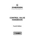
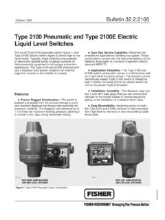
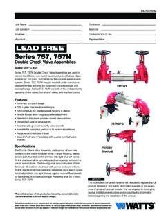
1 9500 Butterfly Control ValveThe Fisher 9500 Butterfly Valve (figure 1 or 2) is afully lined Valve for use with corrosive fluids andwhere tight shutoff is required. The nitrile or PTFE liner totally isolates the Valve body and shaft fromthe process fluid and maintains excellent shutoff atpressure drops to bar (220 psi), andtemperatures to 121 C (250 F).The 9500 Valve is available in NPS 2 through 12 andis compatible with ASME CL125B, with CL150 and CL300, or with DIN valves are furnished with splined shafts foruse with power actuators (figure 1 or 2), with aFisher 1077 manual actuator, or with a 1078declutchable manual actuator (see figure 3).W9224-1 Figure 1. Fisher 9500 Valve with 1052 Actuator andFIELDVUEt DVC6020 Digital Valve ControllerW4082/ILFigure 2.
2 Fisher 9500 Valve with 1066SR ActuatorProduct :9500D100058X012 September 20069500 Valve9500 ValveProduct : 9500 September 2006 2 SpecificationsValve SizesNPS J2, J3, J4, J6, J8, J10, or J12 Valve StyleFlangeless (wafer-type) Valve to be installedbetween two pipe flangesEnd Connection StylesFlangeless (wafer-style) Valve mates with CL125flat-face flanges per ASME , CL150 andCL300 raised-face flanges per ASME , orDIN flanges as shown in table 2 Maximum Allowable Inlet Pressure(1)Maximum material temperature capabilities arelimited as shown in table 3. The materialmaximum allowable shutoff or flowing pressuredrop limits are shown in tables 1 and 4. Valvebodies are consistent with applicablepressure/temperature ratings for JCL125B perASME , or JCL150 and CL300 per ServiceValves suitable are for vacuum service toapproximately 10-7 mm Hg absolute ( x 10-12mbar, absolute)Maximum Allowable Pressure Drop(1)Maximum Allowable Shutoff: See table Flowing Pressure Drops: See table 4 Construction MaterialsValve body: JCast iron, Jcarbon steel, orJS31600 [316 stainless steel (SST)]Disc and Liner: See table and Taper Pins: S17400 (17-4PH SST)standard or S20910 Thrust Bearing: All cast iron or steel valves usea PTFE/bronze in a carbon steel shell; NPS 2through 6 SST valves use a PTFE-liner in aS31600 shell.
3 NPS 8 through 12 SST valves usea PTFE-liner in a fiberglass shellThrust Bearing Sleeves: Stainless steelShaft-Seal Thrust Plate: JPlated carbon steel(standard) or JS31600 SSTT hrust-Plate Cap Screws: SteelMaterial Temperature Capabilities(1)See table 3 Flow CharacteristicConventional Disc: Approximately equalpercentage through 60 degrees of disc rotationFISHTAILt Disc: Approximately equalpercentage through 90 degrees of disc rotationFlow DirectionConventional Disc: BidirectionalFISHTAIL Disc: Forward flow The tail of the discopens into the downstream end of the valveFlow CoefficientsSee the section titled Coefficients in this bulletinor Catalog 12 Flow Coefficient Ratio(2)Conventional Disc: approximately 33 to 1 for a 0to 60 degree disc rotationFISHTAIL Disc: 100 to 1 or greater for a 0 to 90degree disc rotationDisc RotationConventional Disc:On/Off Service: J0 to 60 or J0 to 90 degreesThrottling Service: 0 to 60 degreesFISHTAIL Disc: 0 to 60 or 0 to 90 degrees foron/off or throttlingNoise LevelsRefer to Catalog 12 for sound pressure levelpredictionShutoff Classification per ANSI/FCI 70-2 and IEC 60534-4 Nitrile or PTFE Liner: Class VIActuator/ Valve ActionField-reversible between Jpush-down-to-open (extending actuator stem opens disc) orJpush-down-to-close (extending actuator stemcloses disc)(continued) 9500 ValveProduct.
4 9500 September 2006 3 Specifications (continued)Actuator MountingMounting configurations are as follows: Actuatorcan be Jperpendicular to (standard) orJparallel with pipeline with actuator to Jright(standard) or Jleft of Valve body (when viewedfrom Valve inlet). With perpendicular mounting inhorizontal pipeline, actuator can extend Jabove(standard) or Jbelow pipeline. With parallelmounting, actuator can extend Jupstream orJdownstream of valveMating Flange CapabilitiesAll sizes compatible with weld-neck flanges; alsosee the Installation section for slip-on flangesFace-to-Face DimensionsDimensions meet MSS SP-67 specifications forface-to-face dimensions of flangeless valvesValve Shaft DiametersSee figure 6 and table 5 Approximate WeightsSee figure 6 and table 5 OptionsThree-Way Valve : For converging or divergingservice.
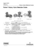
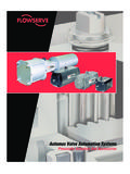
5 Consists of two 9500 valves and a singleactuator mounted on a pipe tee. Actuatoroperates both valves through tandem your Emerson Process Managementsales office sizing informationFlange Adapters: Provide additional liner supportfor use with Jslip-on flanges and Valve bodiesNPS 6 and larger, Jflexible flanges, Jflangeshaving inside diameters less than or greater thanstandard weld-neck flanges, or for Jdead-endservice ( Valve installed at end of pipe run) Valve body for mating between CL300 Actuator: Fisher 1077 manualhandwheel rotary actuator, or the 1078declutchable manual actuator, see figure 31. The pressure/temperature limits in this bulletin and any other applicable standard or code limitation should not be Ratio of maximum flow coefficient to minimum usable flow MANUAL ACTUATOR1078 DECLUTCHABLE MANUAL ACTUATORF igure 3.
6 Fisher 1077 and 1078 Manual Rotary Actuators9500 ValveProduct : 9500 September 2006 4 Table 1. Maximum Allowable Shutoff Pressure Drops(1) Valve SIZE,NPSMAXIMUM ALLOWABLE SHUTOFF PRESSURE DROPSL iquid ServiceGaseous ServicePTFE LinerNitrile LinerPTFE LinerNitrile LinerCast IronValveMaterialSteel orStainless SteelValve MaterialCast IronValveMaterialSteel orStainless SteelValve MaterialCast IronValveMaterialSteel orStainless SteelValve MaterialCast IronValveMaterialSteel orStainless SteelValve MaterialBar2, 3, and , 8, 10, and , 3, and 41752201752201752201752206, 8, 10, and 121752201501501752201501501. The values in this table were determined using S17400 (17-4PH SST) shaft and taper pins. If other materials are used, you must refer to Catalog 14 Pages (section D) for Conventional discs are available forbidirectional, on/off or throttling Control .
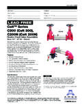
7 valves areavailable with S31600 [316 stainless steel (SST)]FISHTAIL disc for on/off or throttling Control (see figure 4). The discs can be obtained in a variety ofalloy materials for additional corrosion Valve body and shafts areisolated from process fluid, allowing use of cast ironvalve bodies for corrosive Shaft Seal Liner is directedagainst a flat disc hub by a thrust bearing, creating aseal between the liner and the disc as shown infigure 5. Seals are adjusted as necessary to provideleak Gasket Not Required Partial O-ring(figure 5) is molded as part of the liner. It sealsagainst mating flanges which eliminate the need forflange Flow Control The conventionaldisc is approximately equal percentage flowcharacteristic through 60 degrees of its rotation.
8 TheFISHTAIL disc has an approximate equalpercentage flow characteristic through a full 90degrees of disc Economy The FISHTAIL discreduces dynamic torque, which allows the use of asmaller actuator size for a given Maintenance No lubrication isrequired, and no packing or flange gaskets toreplace. Shaft seal is easy to adjust. Removing valvecomponents and changing the Valve action isaccomplished without complete slip-in liner minimizes downtimeand reduces maintenance ValveProduct : 9500 September 2006 5 Table 2. Mating Flange CompatibilityVALVE SIZE,NPSCAST IRONSTEEL ANDSTAINLESS STEELASMEDINASMEDIN2, 346, 8, 1012 Class 125 BClass 125 BClass 125 BClass 125 BPN10 PN10 Class 150 Class 150 Class 150 Class 150PN16PN16PN16PN16 Table 3.
9 Disc and Liner MaterialsDisc StyleDisc MaterialLiner MaterialTemperatureRange C FConventionalAluminum bronzePTFE-lined elastomer molded toaluminum backup ring 18 to 1210 to 250 Nitrile molded to hard rubber backupring 7 to 9320 to 200 FISHTAILS31600 stainless steelPTFE-lined elastomer molded toaluminum backup ring 18 to 1210 to 250 Table 4. Maximum Allowable Flowing Pressure Drops Due to Strength Capabilities of Valve Body ComponentsVALVE SIZE,NPSMAXIMUM ALLOWABLE FLOWING PRESSURE DROPSC onventional DiscFISHTAIL DiscAt 60 Degrees RotationAt 90 Degrees RotationAt 60 Degrees RotationAt 90 Degrees (1) (2) (1) (2) (1) (2) (1) (2) (1) (2) (1) (2) (1)220(2)124175(1)220(2)175(1)220(2)3175 (1)220(2)73175(1)220(2)175(1)220(2)46810 1296505025293116168917385854147994242171 91.
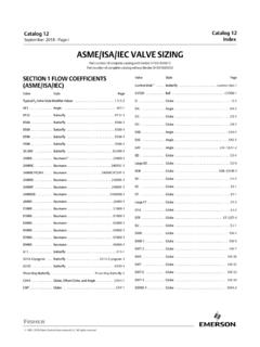
10 For cast iron Valve For steel or stainless steel Valve ValveProduct : 9500 September 2006 6W1628-2*/ILW1627-2*/ILNITRILE LINERPTFE LINERALUMINUM BACKUP RINGNITRILE MOLDED TOINSIDE DIAMETER ANDSIDES OF BACKUP RINGTHRUST BEARINGFISHTAIL EDGEOF DISCTAPER PINSHAFT-DISCCONNECTIONALUMINUM BACKUP RINGRESILIENT ELASTOMERMOLDED AROUND BACKUPRINGTFE LINING ON INSIDEDIAMETER, SIDES, ANDSHAFT HOLES OFELASTOMERTHRUST BEARINGF igure 4. Sectional Views of Fisher 9500 ValvesW1628-2*/ILTHRUSTPLATEVALVEBODYBAC KUPRINGFLAT HUB OF DISC AND LINERNITRILE LINERPARTIAL O-RINGTHRUST BEARINGF igure 5. Adjustable Hub Seal DetailsInstallationPlease refer to the Fisher 9500 instructionmanual, D100380X012, for additional / completeinstallation and maintenance valves may be installed in any position.